[Trade Journal]
Publication: The Journal of Electricity, Power and Gas
San Francisco, CA, United States
vol. 11, no. 8, p. 195, 198-202, col. 1-2
THE BAY COUNTIES TRANSMISSION LINE.
BY C. E. DUTCHER.
AS the design, construction and installation of generators, transformers and motors has been brought to such a state of perfection as to guarantee absolutely continuous and successful operation at very high efficiencies, it has been the aim of the Bay Counties Power Company to bring its pole lines to an equally high degree of efficiency in every possible sense. For this reason it was decided to install a double pole line throughout the entire length of its bay line, from the power-house at Colgate to the city of Oakland, so that should one line go down from any cause, the service would still be continued uninterruptedly over the other line until repairs could be made. The company did not stop with a double pole line, however, in its endeavors to make the transmission link of its system the best that could possibly be devised, for throughout there has been selected and used only the best of material and workmanship in order to guarantee and insure uninterrupted service.
| |||
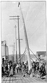
| Eight Men Are All That Are Required to Raise A 60-Foot Pole. |
All poles are set one foot deeper in the ground on angles. The poles are shaved the entire surface of the top to a point six inches below the bottom cross arm, and are painted with a tar paint put on hot, which gives it the glossy finish that is the identifying characteristic of the Bay Counties lines. The butts are saturated with hot carbolineum, imported from Germany, for a distance of two and one-half feet below what is known as the "air line" and one foot above. The poles are framed and cross armed so that the three wires of each three phase circuit form an equilateral triangle thirty-six inches on the side and forty-two inches on transpositions, each line being transposed every mile. This transposition consists of one-third of a turn or spiral, that in one line being to the right, while that of the other is to the left. In other pole lines it has been found that although the pins may have been amply separated for straight line work, the twisting of the lines at the transpositions brought them so near together at the center of the transposition span that they have been shortened even by such small birds as meadow larks. This occurrence has been avoided in the lines under consideration by making the sides of the triangle six inches greater on transposition arms than on ordinary runs, which brings the minimum separation between transposition poles down to thirty 6 inches. The poles are of Oregon cedar, round, and in length as follows:
 |
Referring to the map of the transmission lines of the Bay Counties Power Company, it will be seen that these lines parallel the railroad only between Cordelia and Davisville, a distance of thirty-three miles, so that by far the greater portion of the line construction was over country that could only be reached by team, and which varied in altitude from practically the sea level to something over two feet, all of it above Arcade being mountainous, while that below Sacramento is over level country until Cordelia is reached, when mountains of varying altitudes up to 1000 feet are crossed before the line reaches Oakland. The extremes of temperature to which the lines are subjected vary from about 26 to 116 degrees.
| |||
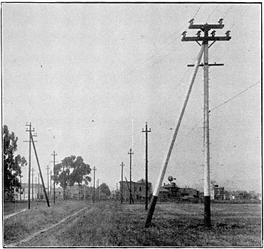
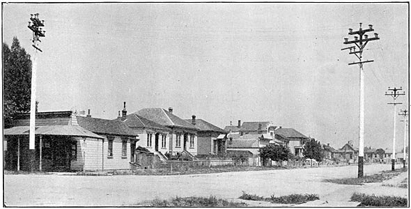
| The Double Poleline Ends at the Berkley-Oakland City Limits. |
The poles are taken from the cars and placed on skidways convenient to frame and again loaded on wagons. This is done by the use of spike skids, a running line a snatch team and one man. This equipment is all that is necessary to load any kind of a pole on to any wagon. The poles are taken along the pole line and delivered with the top up hill and the butt of the pole at the hole, which procedure does away with the handling of a pole the second time. After the cross arm is put on and the pins are nailed in, the pole is ready to set. This is done in three lifts by 8 men who are trained to work together and who pike and tamp-in 40 poles per day. As stated, most of the lines are over a mountainous country altogether inaccessible to a truck derrick, and the skill which the men have acquired in piking-in poles has become so remarkable that my preference is most decidedly for piking rather than derricking. In piking each man knows his position and he does his work with mechanical precision without a word being said or a motion made. In the first lift the pole is placed on to a six-foot deadman, as the short crosshorse is termed; in the second lift the pole is raised by the short pike men, while the third lift puts it into the hole, when it is caught by two long sixteen-foot pikes, one on each side, while in the vertical position. Then the two fourteen-foot pike men walk around to the sides of the pole and stay it so that by the time the "straw boss" has reached the butt of the next pole to sight the line, the short pike man is off to the side at right angles to the line, when the pole is finally set by the plumb bob and tamped-in.
| |||
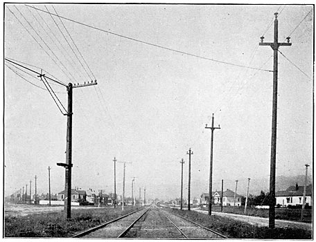
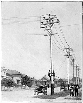
| At Lorin May Be Seen A Transposition and A Railroad Crossing. |
Pole hole digging is one of the most important portions of line construction, and it forms a trade by itself which few become proficient in. All pole positions are "spotted" by one man, who does no other work. He carries a pick and shovel and digs a hole about a foot deep on the exact spot indicated by the surveyor's stake, the diameter of the hole being greater than that of the pole at the ground line by sufficient space to admit the use of a four-inch tamp bar. It is of the greatest importance that the pole holes should be uniform in shape, and especially is this true if soft ground is being worked. Practically all the holes were "shot," that is, blasted out, for in general the character of the ground worked was either hard pan or hard or soft rock. Bearing these points in mind it is easy to see that the "powder monkey," to be proficient and economical in the use of powder, must be possessed of good judgment and great experience. In fact, it is astonishing to see how expert a "powder monkey" can become. After the hole has been spotted, he knows at a glance the character of ground that he is to shoot out; if it is hard pan or doby he uses an one-inch auger, if it is hard or soft rock, he uses a drill and hammer, drilling down from twenty-four to thirty inches. No. 2 Hercules giant powder is used in quantities varying from one-half to two and one-half sticks per hole, according to the character of the ground, and in shooting out a five-foot hole in the ordinary ground encountered, the amount of powder used and the position or method of its use is gaged so skillfully that the ground will be loosened to within two inches of the depth desired. Any remaining dirt is barred out, ten foot thirty-five-pound bars being used. Of course no definite statement of the number of holes a man can shoot in a day can be made for the reason that the character of the ground is altogether too varied to enable any estimate to be formed, but just enough hole diggers arc used in a construction crew to keep ahead of the pole setters and wire gang, so that all of the work shall go ahead together. The setting of forty poles is regarded as a day's work for a crew, that is, a single crew must dig the holes, frame, set and string the wire on forty poles under ordinary conditions, and this crew will consist of one hole spotter, two "powder monkeys" with sufficient hole diggers behind them to keep clear of the pole crew, eight men in the pole crew, five climbers, two reel men and two men on the blocks.
| |||
| Head and Strain Guying A Live 40,000-Volt Line. |
| |||
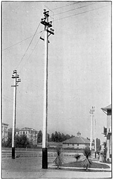
| A Double Corner at Twenty-Seventh and West Streets, Oakland. |
The main line consists, as stated, of two pole lines, one of which carries No. 00 B. & S. gage medium hard drawn copper and the other carries No. 0000 seven strand aluminumthe equivalent of No. 00 copper. Joints in the copper lines are of the Western Union type with nine wraps on the side and an inch neck, soldered the entire length. Joints in the aluminum line are of the standard form, consisting of a right and left hand-screw conical shaped joint with the center or core wire of the cable turned back upon itself and the joint being filled with solder after being set up tight. No wedge is used, as every function of the wedge is filled by turning back 1-1/2 inches of the No. 4 core wire. A team of horses on a watch tackle were not able to pull this joint apart.
The copper runs about 1,400 feet to the coil, two such coils being placed on the reels, when the lines are drawn out by horses. Transpositions are laid out on the ground. All this is being done while the linemen are tying in the last stretch. Then when the linemen get tip to where the blocks are, they put on the temporary head guy to hold the line up and the blocks are taken off and sent ahead. Then the line men raise the wire up on the crossarms by the heaving lines which they carry, while in the meantime the same team has gone on ahead and has been hitched on to the blocks. The other line wires are then pulled up together by the team through a set of equalizers on the blocks. The lines are pulled up taut and then dropped back through the equalizers until the proper drop or sag has been reached,this sag being 18 inches in the valleys, 22 over the hills, and six inches more around angles than on the straight line. Due allowance from these figures is of course made for temperature variations. Head braces are used on all heavy angles to hold the corners, and double construction is used on all road and railroad crossings and angles. No metal is used in head, strain, or anchor guys except with at least thirty feet of wood insulation intervening between the line wires and the ground. All braces run to cross arms, and it has been demonstrated that while the pole will heave if pole braces are used one-third below the top of the pole, braces will not cause heaving of pole if placed at the cross arm.
| |||
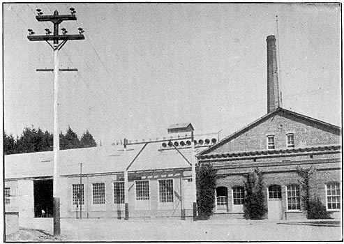
| Piedmont Sub-Station, Oakland, Showing Method of Entering High-Tension Lines. |
| |||
| Two Corners, With 60-Foot Square Poles, on the Standard Tie Line. |
All changes in the elevation of the line are led up to by grading, and crossings over railroads clear the track by 42 feet to the transmission line. An aluminum stranded cable, No. 4 B. & S. gage, is placed on a cross arm 5 feet below the power arm of the copper line. This telephone line, which is not transposed, is supported on double petticoat deep groove glass insulators separated four feet.
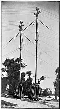
Some notable spans, other than the one across the Straits of Carquinez, occur on the line, and the features of these are shown in the accompanying illustrations and drawings. At Vernon, in Yolo county, two spliced masts, 125 feet high, carry the lines across the Sacramento river in a span of 800 feet. No. 00 hard drawn copper is used for making the span, and the distinguishing feature of the masts are the 20 foot sticks of Oregon pine, 6 inches square, that are inserted in the guy lines for insulation purposes. The span wires run in trunnions of lignum vitae, supported on insulator tops, as shown in the drawing. The grading in the lines from these masts is a nice piece of work. The lines are carried down first to a 6o-foot pole carrying a double "buck arm which in turn supports a transverse arm carrying four standard pins and insulators, all placed in line and to which the line wires are tied. Next follow in succession 50-foot, 45-foot, 40-foot and 35-foot poles each similar to the 6o-foot pole so far as the cross arm arrangement is concerned, but the 50-foot pole carries three insulators, while the 45-foot pole as well as the others, carry two insulators all on double arms. This arrangement gives ample anchorage. The clearance of this span is 85 feet and its sag is 27 feet.
| |||
| Crossing the Feather River at Verona. |
| |||
| The Putah Creek Crossing. |
| |||
| Looking North From Verona Masts. |
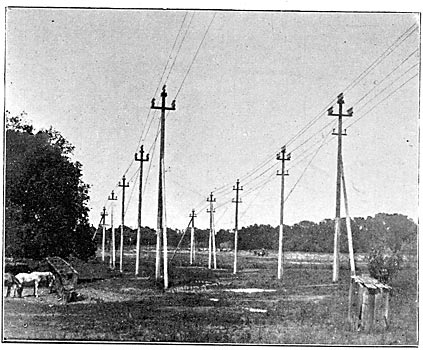
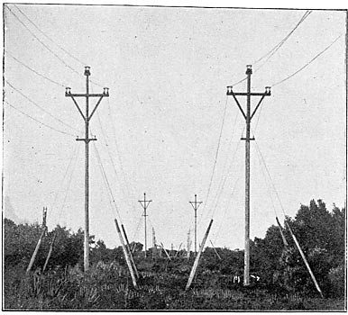
Another notable span is that crossing the Putah Creek, more commonly known as the Davisville Canal, near Davisville. Its details are shown so fully in the accompanying drawings that further explanation is unnecessary. In fact, it seems almost idle to add any explanatory words concerning the features of Bay Counties pole line construction which the accompanying engravings illustrate. The double pole line continues through from Colgate to the North Tower, where the circuits are thrown together and then carried across the great Carquinez span** as a single three-wire three phase circuit, to the South tower, whence a double pole line is continued through to the city limits between Berkeley and Oakland. The style of transposition used is illustrated in the Grove street, Berkeley and the Lorin views, and the Lorin photograph also shows the use of 6D-foot poles in crossing the Berkeley local track of the Southern Pacific Company. The method adopted for bracing corners is shown admirably in the view of the terminus of the double pole line and the beginning of the single pole line. Where poles are placed at angles in the line, the possibility of trouble arising from any line pulling off its insulator, is believed to have been: precluded through the use of "safeties," as may be seen in four of the engravings. These "safeties" consist of one-half-inch gas pipe bent around the circuit in the direction of pole in the manner shown, the ends of the gas pipe being secured to the tops of standard Locke high tension insulators, one of which is mounted on the top of the pole, and the remaining two at the lower end of the safety, being mounted in a special cross arm. It is about a mile through the city of Oakland from the Piedmont sub-station to the Grove street sub-station of the Standard Electric Company of California; and these two sub-stations are tied in by means of a single pole line of square sawed redwood poles, sixty feet in height and carrying a single 40,000 volt three-phase circuit. The six-power cables from Colgate enter the Piedmont substation through the six terra cotta sewer pipes toward the left of the view of the Piedmont station, on page 170 of the last issue, and the three tie-in lines to the Standard sub-station come out through the remaining three terra cotta pipesall through the intervention of a framing supporting double insulators.
One other photograph deserves special consideration, and that is the one illustrating a crew of men placing head and strain guys on 50-foot poles in Oakland, while the transmission line is carrying 40,000 volts in regular service and while the telephone cables are altogether too "hot" for physical comfort. In this work, the men work in pairs, and each man uses hut one hand, so that the pair of two men really perform but one man's work. Added safety is thus secured, but I assure you that the sensations experienced by these men working with their hair constantly standing bolt upright, in frenzied response to the commands of the static charge of the line, is not altogether comparable to the delectations possible from the mingled combination of an inviting shade, a long iced drink and a red-hot summer's day.
 |
| Detail of Mast on Sacramento River at Vernon. |
 |
| Details of Cable Crossing at Bear River. |
 |
| Details of the Framing at the Feather River Crossing. |
 |
| Head and Foundation Details of the Putah Creek Masts. |
* Submitted for discussion at the Fifth Annual Convention of the Pacific Coast Electric Transmission Association, San Jose, Cal., June 18-19, mot.
** Described in THE JOURNAL for May, 1901, Volume XI, page 91, et seq.
