[Trade Journal]
Publication: The Journal of Electricity, Power and Gas
San Francisco, CA, United States
vol. 11, no. 8, p. 185-195, col. 1-2
Some Details of High-Tension Pole Line Construction.
BY C. O. POOLE.
STEP by step the natural power of our mountain streams has been brought closer to our factory doorsall through the energy and enterprise of our capitalists and the ingenuity of our engineers. The engineer makes this feasible and the capitalist converts the projects of the engineer into practical realization. Ten years ago if any one had suggested the use of 40,000 volts for a commercial purpose his mental condition would have been looked upon with suspicion and pity, yet this voltage has been in practical use for several years, and it has recently been demonstrated that the use of 60,000 volts is entirely feasible, while to my mind it seems quite possible that the near future will see even higher voltages than this in practical operation. The two limiting features in high-tension work are transformer design and line construction, and as it is quite possible to connect transformers in series to obtain extremely high voltages, it seems that the principal limiting feature is the line. I will give a brief description of the pole line construction adopted by the Standard Electric Company of California, confining myself principally to the mechanical construction, leaving the more complex electrical phenomena in other hands.
 |
| Standard Insulator, Cable and Tie. |
The poles used by the Standard Electric Company are all of sawed redwood and are taken from the hearts of young trees. Not more than four poles are taken from any one tree, there being no sap whatever in the finished poles. The heights and sizes, together with the depths to which the poles are placed in the ground, are given in the table appearing on the following page.
 |
| Figure 1. |
 |
| Figures 2 and 3. |
In places where the ground is very soft and the tamping is not good the poles are set from 6 inches to one foot deeper than the depths given in the table. For crossing soft marsh land there is used what is termed a "bottom construction," which consists of a kind of maltese cross arrangement, made by spiking redwood pieces 2 inches by 8 inches by 8 feet long on all four sides of the pole, as shown in Figure 1. This construction is placed just below the ground, and a great weight of sod and earth is piled on top of it, reaching up the pole for a distance of about 3 feet. The plan has proven very satisfactory, having resisted the severe wind storms of last winter much better than some of the poles planted in firmer ground. On all angles greater than two and a half degrees the poles are double constructed and strutted. On ordinary angles the strut is placed on the inside of the angle, and is fastened to a deadman buried in the ground to a depth of from 4 to 5 feet, as shown in Figure 2. On extreme angles the strut is used as an anchor, placing the anchor on the outside of the angle instead of inside, as in the previous case. This construction is shown in Figure 3. It has been found by experience in our work that on heavy angles when the ground is wet and the wind is severe that in the strut arrangement shown in Figure 2 the pole has a tendency to ride the strut, and in some cases the pole has been pulled out of the ground. The arrangement outlined in Figure 3, however, overcomes this difficulty, and I have yet to find one of them that has given away in the least. Wherever circumstances permit, severe angles are taken on two double constructed strutted poles, dividing the angle between the two poles.
| |||
| Poles Are Strutted on Heavy Curves. |
| |||
| These Struts Are Used in Oakland Angles |
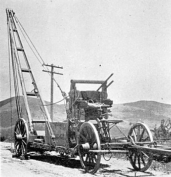
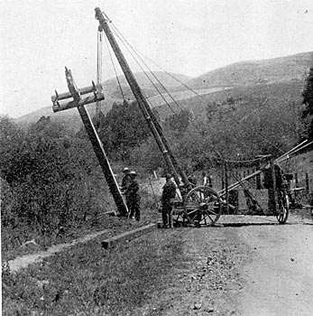
For raising the poles we use a truck derrick, that is, a derrick mounted on the rear end of a low four-wheel truck, which is equipped with a windlass for controlling the position of the derrick. The truck is backed up to a position close to the pole and a sling is placed around it near the middle of the pole, to which the block is attached. The fall passes through a snatch-block fastened to the wheels of the truck and the horses walk out along the line, raising the pole in position to drop into the hole. In places where the truck cannot be taken the men pike?in the small poles and use a gin pole for the larger ones.
 |
| Figure 4. |
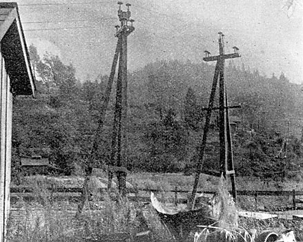
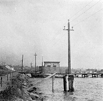
On extremely bad ground where there is "no bottom," as the saying is, we have resorted to the use of piles, in some cases using one pile, in other cases two piles, and in one place where the line was forced out into the Bay of San Francisco, so to speak, three piles were used for supporting each pole. The three different methods are shown in Figure 4. This method of construction is rather expensive, but it offers the only solution for a difficult problem. The illustrations give two views of the three-pile bottom as erected.
| |||
| Three Piles Are Generally Used. |
| |||
| Pole-Supporting Piles in East Oakland |
 |
| Figure 5 |
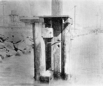
Where the poles are supported over water, platforms 4 feet square are built around the bases of the poles at the top of the piles to facilitate line construction and repairs. These platforms are reached by a light board 10 feet long, which spans the distance between the platform and the railroad trestle, inside of which the poleline extends. Where the line crosses-salt marsh lands, which are flooded by high tides, an elevated walk has been built for the patrolmen. The construction of this walk is shown in Figure 5, in which the 4x6 posts are driven into the ground at a distance of sixteen feet apart with a heavy maul. This distance is spanned with a foot plank, as shown in the figure, having 2 inch by 6 inch pieces spiked to its edges. The plank is sprung up in the center for a distance of about two and a half inches, thus making a truss of each plank. This construction has proven very satisfactory and is quite inexpensive to build.
| |||
| Patrolmen Use An Elevated Walk Over Marsh Lands. |
 |
| Figure 6 |
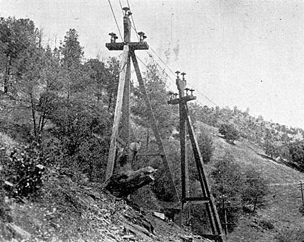
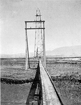
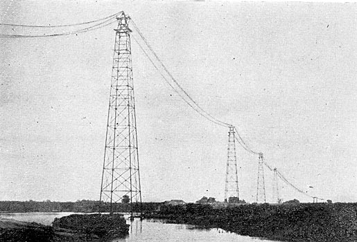
There. are several places where the Standard Electric Company's line crosses navigable streams. As the Government requires a clearance of not less than 115 feet above high water, we had to look to something other than poles to make the crossings. The longest span encountered was 618 feet, in which the sag in the line is 19 feet. Allowing 12 feet for a second line to be run later, makes the total height 146 feet. The method adopted for crossing these streams is shown in the photo-engraving on page 189. At this particular point there are three streams that require the 115-ft. clearance, and four steel towers were used to make the crossings. These towers are 150 feet high and are designed to carry two circuits of three wires each, one circuit being placed above the other. Figure 6 shows the construction of the tower tops, which are made of seasoned Oregon pine. As shown in the drawing, the cable strains are taken on four and six insulators. The crossarms (or rather the longitudinal arms in this case) are shaped to fit the curve of the cables so as to divide the strain on the insulators. Some of the towers were compelled to take a horizontal angle, and in order to equalize the strain on the insulators and pins the arms were curved both vertically and horizon-'tally, as shown on plan in Figure 6.
| |||
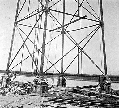
| Piling Supports the Tower Framework. |
| |||
| The San Joaquin River is Crossed Over Four Towers. |
 |
| Figure 7. |
As the ground in the location of the towers is very soft, it was found necessary to use piles for foundations. The base of the tower is in the form of a quadrangle 25 feet square. Under each crossing are driven four redwood piles 16 inches diameter at their butts. The four piles are driven as a solid cluster, securely bound together above ground with steel cables. The tops of the piles are sawed off on a slant to suit the batter of the tower members and capped with a cast-iron shoe bedded on a piece of sheet lead. A galvanized iron bolt 2 inches in diameter passes through the cap and down into each pile for a distance of about 4 feet, the nut and washer for the lower end being mortised into the pile. The detail of this work is shown in Figure 7, as well as in the accompanying halftone. As the cables leave the towers they -drop to wooden take-offs, located about 550 feet distant from the towers. The construction of these take-offs is shown in Figure 8. The take-offs consist of two 40-foot poles strutted two ways with mudsills for supporting the struts aid tying the frame together.
 |
| Figure 8. |
Haying described the pole line from a ground man's point of view, let us now put on our spurs and see what is going on at the top of the pole. The old-time lineman climbs the pole as far as the telephone arm. Then he looks up and hesitates, and giving his spurs an extra jab into the pole, he throws his life belt around the pole and leans back, still looking up and soliloquizing: "Well, I'll be switched! I wonder if they've got a cable road up there. They've got a railroad tie for a crossarm, table legs for pins, a Chinaman's hat for an insulator, and a full-grown street railway cable for wire. That's too much for me!"
I think you will agree that the lineman is not very much to blame for his surprise, for the Standard line is certainly radically different from the pole lines of a few years ago. The line was designed to carry 60,000 volts with safety, and as a single circuit is to carry 10,000 horsepower a distance of 150 miles at less than to per cent. drop, the conductors must necessarily be large. This acids to the problem a mechanical difficulty not heretofore encountered.
 |
| Figure 9. |
The main line, consists of three aluminum cables, each 7-8 of an inch in outside diameter and made up of 37 strands, having a total cross section of 471,034 circular mils. The weight per mile is 2404 pounds, and the resistance per mile is 0.205 ohms. This cable is all specially drawn and laid right and left hand. Its tensile strength of the cable is 28,000 pounds per square inch. In stringing the cable the deflections given were calculated for a Maximum strain of 4000 pounds per square inch, giving a factor of safety of seven at 20 degrees F. The very high co-efficient of expansion of aluminum requires careful consideration in stringing aluminum wire. The first impression one is likely to have of an aluminum line when seen on a hot day is that it is about time for the lineman to come along and cut out some slack, but if one sees the same line on a cold, frosty morning he will feel very much as though some lineman should cut in slack, instead of taking it out. A 132-foot span, having a deflection of 33 inches at 100 degrees, will have a sag of but 13 inches on a cold morning. Figure 9 is a table of deflections for different spans and temperatures, based on a mechanical strain of 4000 pounds per square inch at 20 degrees F. In this will be noticed the fact that there are two sets of temperature figures. The upper set I have called "mountain temperatures" and the lower set "valley temperatures." In the table the figures are simply shifted 10 degrees to the left, which gives about 8 per cent. less sag in the valleys, where the temperatures are less likely to reach the 20 degree mark.
| |||
| The Low, Four-Wheeled Truck Derrick. |
| |||
| The Truck-Derrick in Action. |
| |||
| Cable is Paid Out From A Special Two-Wheel Reel Cart. |
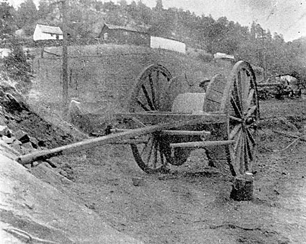
It might he of some interest to know how the large cables are handled. The cable is shipped from the factory on hardwood reels, each reel containing a cable one mile in length. Wherever the ground would permit, the reel would be mounted on a stand and the reel-stand placed on the rear end of a low four-wheel truck. The team would then be driven out along the pole line, paying out the cable as the truck went along. A brake is used on the reel to steady the paying-out process. After the cable is laid out on the ground, the linemen, with hand ropes, haul it up on to the crossarm. On one section of the line a special two-wheel cart was used for paying out the cable, and it proved to be quite satisfactory. The illustration gives an idea of the cart, which was so designed that the wheels could be taken off easily and the axle slipped through the center of the reel, using the axle for a reel-shaft.
In the rough mountain districts the men were forced to use the time-worn method of pulling out over the arms, sometimes using a team of horses for pulling the cable out, and at other times resorting to their good brawn in places where a goat could hardly find a foothold. Our plan of work is to lay out several miles of cable over the crossarms and then place the cable on the insulators. Each gang foreman is provided with a handy, accurate thermometer. Each lineman on the poles has a sighting target, which hangs from a cord that is knotted every two inches. These knots fit into a small brass hook, which is hung on the wire close to the insulator. The blocks and falls are then put on, one wire at a time, and from six to eight spans are pulled up at once. The foreman, after consulting his thermometer, gives the number of the knot to be placed on the hook, and the lineman on the crossarm sights from his target to his comrade's target on the next pole. When the slack of the line reaches the line of vision, he sings out and then ties in. This is repeated from pole to pole until the six spans are completed, when the blocks are moved ahead and made ready for another stretch.
The size of the wire used for tying the large cables is No. 1 solid aluminum, and for cables 1-2 inch in diameter and under, No. 4 aluminum is used. Our method of tying is somewhat different from any that I have seen in use, and we have found it to be very efficient. The line can be dead-ended at any pole, and the tie will hold the line without slipping. The initial engraving shows the method of tying. In very hilly sections where the line pitches up and down and the wire is thrown out of a true catenary curve, the table of deflections cannot be used. In such cases the foreman must use good judgment in allowing slack enoughthe tendency is to be a little bit too economical with his wire. In several cases we have had to make more slack by raising or lowering poles, as we have preferred this method to cutting and splicing the cable. We also make a practice of allowing a little extra slack on had corners, so as to ease them during cold snaps.
 |
| Figure 10. |
The method of joining cable is quite an important feature, and the final selection of the joint used was determined only after extended experiments. Figure 10 shows this joint, and it may be added it has proven most satisfactory under most trying conditions. In testing the joint, the cable invariably broke just outside the joint before it would pull through. As will be seen from the cut, it is a right and left hand screw joint, in which the two male parts are cupped out large at the thread ends.
The method of joining the cable is as follows: The cable is cut off square with a hack saw and the end passes through one of the male parts. About one inch of the ends of the cable strands are turned back upon themselves and the knot thus formed is forced back into the socket, when a small tapered aluminum plug is driven into the center of the knot, filling the socket completely. The other part is treated in the same manner, the nut is then screwed on, which draws the cable ends together and makes a firm and solid joint. The resistance of the joint is less than the resistance of an equal length of the cable.
We now come to the most important of all the important features in high-tension transmission workthe insulator.
Without tiring you with the details of the development of the insulator that the Standard Electric Company is using, I will state briefly that at the time we adopted it there was nothing on the market that would anywhere near meet our requirements, hence it was not until after many months of cut and try methods had passed before we obtained an insulator that would stand the exacting test to which it would be subjected. Figure 11 shows the Standard insulator in section and perspective, and the initial illustration shows it as erected. It is what is called a two-part insulator, the upper part being of porcelain and the lower part of glass.
| |||
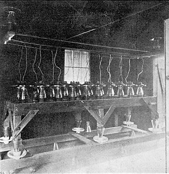
| Testing Insulators at 120,000 Volts. |
| |||
| Insulators Under Test at the Grove Street Substation Showed Dark Flashes at Times. |
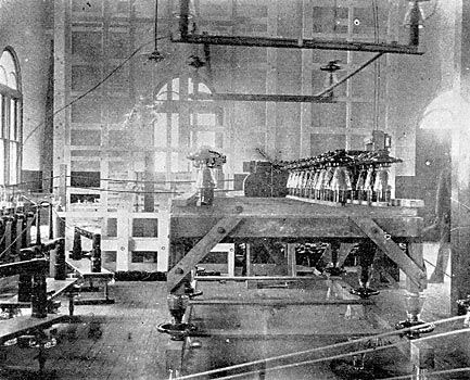
There are several reasons why a combination insulator was decided upon. First, the dielectric strength of the glass is greater than an equal thickness of porcelain, while, on the other hand, moisture clings less readily to the porcelain. It was also found that a much cheaper insulator could be made in this way than making it either wholly of glass or of porcelain. As a matter fact, the insulator as designed could not be made of glass in one piece. The two parts of the insulator are cemented together with a cement composed of sulphur and sharp sand in about equal parts. After being cemented together, every insulator is subjected to a test of 120,000 volts for a period of five minutes, and if any insulator shows a sign of weakness it is rejected. In testing the insulators,* the pins upon which the insulators are mounted are hollow and a wire leads up through the pin, terminating in a spiral spring at the top of the pin. This spring projects about an inch above the top of the pin. The pin is capped with a piece of sheet copper, about one inch in diameter, to present a good contact surface for the insulator to rest upon. The insulators are then placed on the pins, resting upon the contact, which is one terminal of the testing set. For the other contact there is used a piece of No. 14 soft copper wire that is fastened tightly around the tie groove of the insulator in the form of a noose and slip knot. Thirty insulators are placed on the testing rack at one time; when the pressure is gradually brought up to approximately 120,000 volts, the spark gap being set at 12 1/2 inches. If an insulator gives away, it is replaced with another one and the pressure is applied again. This process is repeated until the nest of insulators stands the test for five minutes. It was found by experience that an insulator after standing the test for five minutes would seldom show signs of weakness when subjected to a longer exposure. This method of testing is very rapid, as two men will test thirty insulators in about fifteen minutes, or an average rate of one-half minute for each insulator. The high-voltaging set** consists of twelve transformers, each giving a pressure of 10,000 volts. The transformers are connected in groups of three on the low-tension side through insulating transformers, the high-pressure terminals being all connected in series. The pressure is regulated by a rheostat connected in series with the low-tension circuit.
*The extraordinary photographic phenomenon of "dark" flashes is brought out in the illustration of the original testing set in a striking manner. When the potential approaches 120,000 volts, vivid sparks leap over from the contact on the tops of the insulators to their pins, and it is these sparks which, though of vivid brightness, are shown in the photo-engraving as being black.C. O. P.
**For details, see THE JOURNAL for July, 1901, Volume XI, page 180, et seg.
 |
| Figure 12. |
The insulator pins used by the Standard Electric Company are made from eucalyptus, or blue gum wood, specially seasoned and treated as follows: The timber is sawed into sticks 3 inches square and placed in a vat of boiling water for twenty-four hours, when the sap becomes thoroughly boiled out, being displaced by the water. The timber is then racked up and air-dried for several months. The wood, after undergoing this treatment, is thoroughly seasoned and is tough and hard as hickory. The timber is then worked up into pins by a machine that completes the pin in one operation. The pins are then placed in a vat of boiled linseed oil, which is kept at a temperature of 210 degrees F. for several hours. The oil penetrates the pins to a depth of about 1-16 of an inch and makes a very good moisture-proof finish. Figure 12 gives the shape and dimensions of the pin. Its largest diameter is 2 3-4 inches, and it tapers to 2 1 -2 inches at the upper shoulder. The diameter at the base of the thread is 1 1-2 inches and 1 3-8 inches at the top, the thread having a taper of 1-8 of an inch in 2 1-4 inches, the number of threads per inch being four. The shank of the pin is 2 1-4 by 4 7-8 inches, and the length of the pin over all is 16 7-8 inches.
 |
| Figure 13. |
Before the pin is driven into the arm, the shank is dipped into P. & B. paint, and some of the paint is put into the pinhole of the arm. A hardwood set is then placed on top of the pin, slipping down freely over the thread and resting upon the shoulder of the pin. An eight-pound sledge is then used to drive the pin home. This method of driving the pins into the arm has proven very satisfactory, for hardly ever has a pin been spoiled. Figure 13 shows the construction of this pin-driving tool. On the base of the pin is used a porcelain sleeve 5 inches long, which rests upon the crossarn and projects up beneath the glass petticoat. The object of this porcelain sleeve is to protect the pin in the event of an arc tending to strike from the eve of the insulator to the base of the pin. It also protects the pin from weathering.
 |
| Figure 14. |
The crossarms are made from selected close-grained and kiln-dried Oregon pine. After boring, the arms are treated with asphaltum oil by placing them in an enclosed boiler under pressure and subjecting them to a temperature, while in the oil, of about 250 degrees F. They are kept submerged in this oil for several hours until the wood is thoroughly permeated with the substance. Asphaltum oil has been found by experiment to be a very good insulator and it is also an excellent wood preservative. The dimensions of the crossarm are given in Figure 14. The distance between the pin holes is 42 inches and the arm is placed on the pole in such a position that the wires form the points of an equilateral triangle having 42-inch sides. The arm is gained into the pole one inch and is held on with two 5-8-inch through bolts with large cast iron washers. It will be noticed in Figure 15 that the pin holes are not bored through, for the reason that one inch of wood was left to add strength to the arm. Figure 15 gives a view of the pole top complete. The top of the pole is beveled off and an iron band 1-4 by 1 1-2 inches is driven on to prevent the pole front splitting. The pin is then driven in as was done in the arm.
 |
| Figure 15. |
Having designed the pole top and secured samples of crossarms, pins and insulators, we may next proceed to determine the weakest point in the combination. In testing, we fitted up a crossarm, pin and insulator complete and then bolted the arm securely to an iron column. A sling was next fastened around the tie groove of the insulator, and, with a dynamometer in circuit with a pull chain, we split the crossarm into pieces with a pull of 1200 pounds. Next a half-inch carriage bolt was put through the arm at a point 3 inches from the center of the pin and 2 inches from the top of the arm, but when the pull was increased to 1800 pounds, the arm split toward the pole. Another 1-2-inch bolt was put through the arm the same distance from the pin toward the pole, but the test applied broke the pin off squarely at the shoulder on top of the arm, at a tension of 2200 pounds. These figures are not taken from a single test, but are the average of a series of tests. The cost of putting the four bolts in the arm, including the bolts, washers, boring holes and ail labor in connection with it, did not exceed to cents per arm, and it fully doubled its strength. All poles carry a six-pin telephone arm placed 6 1-2 feet below the power arm.
The telephone line consists of a No. 8 B. & S. iron wire, which is transposed every four poles on a single transposition insulator. The power line is not transposed at all. Provisions are made for opening the power line at several points in case of trouble by means of switches in specially designed switch-houses.
Figure 16 shows a pole top that has been recently adopted for the 10,000-volt mountain circuits. This method of construction permits of two separate circuits being carried on the same pole in the form of an equilateral triangle, and either circuit can be safely handled while the other is hot.
I am indebted to Mr. A. C. Bunker, the Stanley Electric Manufacturing Company's engineer, for the privilege of describing his design of pole tops. Mr. Bunker will be pleased, I know, to give any further information on the subject that I may have overlooked.
* Submitted for discussion at the Fifth Annual Convention of the Pacific Coast Electric Transmission Association, San Jose, Cal., June 18-19, 1901.
