[Trade Journal]
Publication: Engineering News
New York, NY, United States
vol. 24, no. 14, p. 230-234, col. 1-3
THE 142 MILE ELECTRIC POWER TRANSMISSION PLANT OF THE BAY COUNTIES POWER CO. CALIFORNIA.
By J. D. Galloway.
The completion of the transmission lines of the Bay Counties Power Co., in the early months of this year, marks an important advance in the long distance transmission of power by electricity. From the powerhouse on the Yuba River, in the Sierra Nevada Mountains, to the city of Oakland, the distance by way of the line is 142 miles, and power is now being delivered in that city for lighting and street railway purposes. Under arrangements with the Standard Electric Co.. of California, whose power plant is not completed, power is also being delivered to San Jose over the company's lines, making the total distance of transmission somewhat over 184 miles.
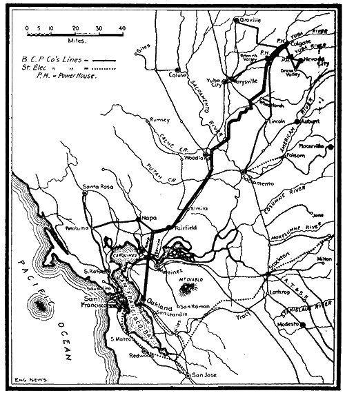 |
| Fig. 1. Map Showing Pole Lines and Distributing Stations of the Bay Counties Power Co. , of California. |
In connection with the construction of this long line there were several features of great engineering interest, the most notable of which is the crossing of the Straits of Carquinez, where the suspended cables have a span of 4,427 ft.
The Bay Counties Power Co. was formed by the consolidation of the Yuba Electric Power Co. and the Nevada County Electric Power Co., two companies under practically the same management, with plants on the South and North Forks of the Yuba River. The initial plant was that of the Nevada County Electric Power Co., which was established on the South Yuba. Work was commenced in July, 1895, and the plant was in operation in February, 1896, delivering 1,000 HP. to Nevada City and Grass Valley for lighting purposes and to various mines for power purposes. In 1897 the capacity of this plant was doubled.
The plant of the Yuba Electric Co., originally the Yuba Power Co., was established in April, 1898, on the North Fork of the Yuba River at a point (about eight miles from Smartsville) where an irrigation canal dropped some 300 ft. This plant was notable for the quick work of the installation, the entire plant being established in four months and five days, 1,500 HP. being developed. This plant delivers power to Marysville, and to mines at Brown's Valley. In less than a year, the demands on the plant led to the building of a larger and more comprehensive system at Colgate. Machinery for the generation of 5,000 HP. was installed, and a line was built to Sacramento, 61 miles distant, and to several gold dredges near Orovllle. The moving spirit in both of these companies was Mr. Eugene J. de Sabla, Jr.
In June. 1900, the Bay Counties Power Co. wat formed by the consolidation of the two above-mentioned companies, and the line to Oakland was projected. In somewhat less than ten months the power plant at Colgate was doubled in capacity, the double pole line constructed 142 miles to Oakland, and the transformer plant and crossing built at Carquinez Straits. On April 27, 1901, the current was turned into the power-house at Oakland.
At present machinery Is installed at the various plants capable of delivering a total of 17,000 HP., and water power Is available for increasing this by 13,000 HP.
Branch lines are built, or are In process of construction, to Woodland, Vallejo, Martinez, Benecia, Napa, Petaluma and Santa Rosa, while various manufacturing establishments are served from the transformer stations at Carquinez Straits. From the station at Oakland, a line about a mile in length leads to the Oakland Station of the Standard Electric Co. of California.
THE POWER-HOUSES IN THE SIERRA NEVADA MOUNTAINS.
There are three power stations situated on various forks of the Tuba River, as noted above, the location of which is shown on the accompanying map. Fig. 1. The plant which supplies power to the Oakland line Is located at Colgate, about 36 miles from Marysville, the river being at this point about 660 ft. above sea level.
The dam across the Yuba River is of timber crib construction, 40 ft. high at the deepest point and about 250 ft. wide on the crest. The controlling gates are set in rubble masonry. In winter the water sometimes reaches a depth of 10 ft. over the crest, and the bed of the river has filled up entirely above the dam with gravel.
| |||
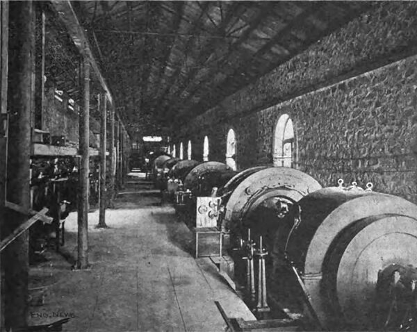
| Fig. 6. Interior of Colgate Power Station. |
The distance from the dam to the penstock on the mountain above the powerhouse is seven and three-quarter mites. The flume which carries the water from the dam to the penstock has a uniform section, 7 ft. wide and 6 ft. deep. The bottom and sides are of 1-1/2-in. plank, with 4 x 6-in. posts and 4 x 8-in. sills, the bents being 3 ft. c. to c. The grade of the flume is 13 ft. to the mile and about 8.000,000 ft., B. M., of lumber was used in the construction. This work, while difficult in places, offers nothing unusual in the way of flume construction.
The penstock is built of rubble masonry, with a lining of concrete 1 ft. thick. The gates to the pipes are inside the penstock, while manhole pipes, protected with conical hoods, are placed just outside. The penstock is arranged to accommodate five lines of pipe, but at present there are but four lines in place. From the penstock to the power-house the distance along the slope is 1,760 ft., the static head in the pipes below 715 ft., and the average angle of slope about 24 from the horizontal. The contour of the pipe is however, somewhat irregular, being considerably steeper in parts.
The upper 800 ft. of the pipes is built of riveted sheet steel, the thicknesses being No. 12 and No. 7, in about even amounts. The lower 960 ft. of the pipe is of cast iron, varying from 1 in. to 1-3/4 ins. in thickness.
Commercial shapes were used, the lengths being 12 ft. When the pipe passed over bed rock it was anchored with steel straps, and at other places it was set in masses of concrete.
The pipes, of which there are four, are each 30 ins. inside diameter, and the effective head of water is 695 ft. The flow is at the rate of 8 ft. per second, with a pressure at the receiver 300 lbs. per sq. in.
The water wheels were made by the Risdon Iron & Locomotive Works, of San Francisco, and are the common type of tangential water wheels. Each generator is driven by a water wheel mounted on the same shaft. The water from the pipe lines enters a receiving pipe, which lies parallel with the power-house and is taken from the receiver in 14-in. pipes to the water wheels. At present the generators for the Oakland line are controlled by hand, but Lombard oil governors are to be installed.
The installation of the present station at Col gate consists of two 2,000 K-W., three 900 K-W., and one 720 K-W. Stanley generators, each direct connected to a water wheel. They are three-phase, 60-cycle, 2,400-volt, inductor machines. There are eight 300 K-W. and four 200 K-W. transformers, the primary winding being for 2,400 volts, and the secondary winding to 24,000 volts. In addition to this there are ten 700 K-W. transformers with primary winding for 2,400 volts and secondary winding arranged to give 40,000, 50,000 and 60,000 volts when connected up in star. All of the transformers are of the Stanley oil-insulated water-cooled type. The station building, 275 x 40 ft., has walls of rubble masonry, with steel roof trusses and galvanized corrugated iron covering. A traveling crane, of a capacity to lift any weight in the building, runs the entire length. Beneath the floor of the building a subway is built containing all the wires which are led to the switching devices at the center of the station. A commodious and well-equipped dwelling house has been erected near the station building for the accommodation of the men.
In connection with the main supply of water an additional supply is being arranged for which is independent of the main river. This is formed by damming up Dobbins Creek to form a lake, which will cover about 90 acres and which has been named Lake Francis. The dam will be an earth fill 75 ft. high. This is now in course of construction, the material forming the dam being hydraulicked into its place. The surface of the lake will be 1,000 ft. above the power-house, and distant therefrom 2-3/4 miles. The lake will be connected with the penstock by 9,000 ft. of 36-in. diameter wooden stave pipe and about 3,000 ft. of steep grade flume.
The Nevada power-house is 7½ miles from Colgate, and supplies power to various points in Nevada County. The plant at this place consists of four 500- HP. generators which deliver a two phase current of 133 cycles and 5,000 volts. This plant is unique, in that two different heads of water may be used on the generators. The ordinary supply, from a flume leading from the Yuba River, has a head of 200 ft. The high head supply has a head of 800 ft., and is delivered from reservoirs with a capacity sufficient to discharge 40,000 miners' inches for 24 hours. Each generator has two water wheels upon its shaft, one using the low pressure water and the other the high pressure.
The Brown's Valley plant, about 9 miles from Colgate, supplies power to Marysville and mines at Brown's Valley. The current generated is two phase, 60 cycles, and at 2,400-volt pressure. The water wheels operate under a head of 392 ft.; Pelton wheels being used. The generators, of which there are two, are of 350 K-W. capacity, and are run at 400 revolutions per minute. Step up transformers, of the Stanley oil-insulated and water- cooled type are used to transform the current to the line pressure of 16,000 volts. The three power-houses above described are all connected with each other, so that the three form a single power station, and the supply of current from any one can be used to help the load on the other in case of necessity.
THE TRANSMISSION SYSTEM AND THE LINE.
The line from the power-house at Colgate to Oakland, as before noted, is somewhat over 142 miles in length. At present the line voltage is 40,000, but this will be increased to 60,000 volts under increased load. Step-down transformers are used at Woodland, Wheatland, Napa, Oak land and at the sub-stations on both sides of Carquinez Straits, which deliver current at the various voltages required at the places mentioned. At Oakland the current is transformed to 2,000 volts, which current operates three General Electric Co. synchronous motors direct- connected to 550-volt direct-current generators of 450 K-W. each. This current is used on the lines of the Oakland Transit Co., which owns all the street car systems of Oakland, Alameda and Berkeley, with a total extent of 126 miles. A branch line carries power to the Oakland central station of the Standard Electric Co, of California. which in turn delivers current to the Oakland Gas, Light & Heat Co.
| |||
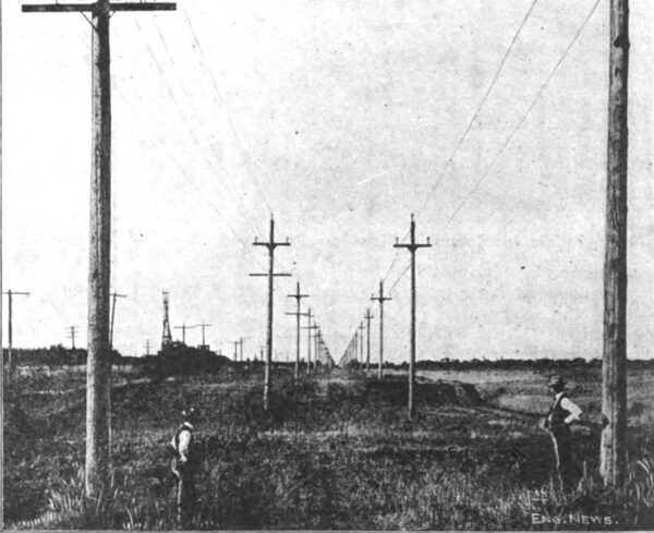
| Fig. 7. View of the Pole Line. |
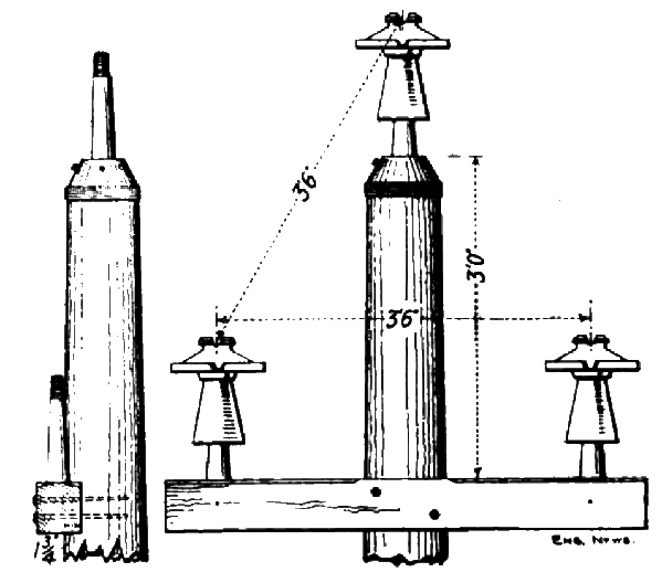 |
| Fig. 16. Details of Pole and Cross-Arm for High Tension Transmission. |
The pole line for the entire distance is in duplicate, the two lines of poles being in general about 25 ft. apart. This duplication was made as an insurance against interruption of the service by accident. One line is of No. 00 medium hard. drawn copper throughout, while the other line is of aluminum from Colgate to Suisun, and of copper for the remaining distance. This was done to avoid the corroding effect of the salt air on the aluminum, in the vicinity of San Francisco Bay. The aluminum cable is composed of seven strands of wire having in total the conductivity of No. 00 copper wire, and was made by the Pittsburg Reduction Co. The standard distance from pole to pole is 132 ft. The poles for the main line are of Oregon red cedar, 14 ins. diameter at the butt and 8 ins. at the small end, and 35 ft. long. They were set one sixth of their length in the ground, the ground end being painted with carbolineum avenarius to prevent decay. The cross-arms are arranged to place the wires at the apices of an equilateral triangle whose sides are 42 ins. in length. The upper end of the pole was coned and bound with six turns of iron wire. The cross-arms were treated with hot asphaltum and coal tar and the upper portion of the poles was painted with tar paint. The line insulators used were made under the patents of Mr. Sterling, the Superintendent of the Bay Division. The pins were of California eucalyptus, boiled in linseed oil.
TELEPHONE LINE.
The telephone line consists of a three-strand aluminum cable having the conductivity of a No. 9 copper wire, and is carried on double-petticoated glass insulators on a cross-arm placed 5 ft. below the power line. The telephone line itself is not transposed, but instead, the power lines are transposed every mile and the very successful operation of the telephone service speaks well for this arrangement. Much credit is due Mr. T. E. Theberath for suggesting this idea.
THE CROSSINGS AT BEAR RIVER, PUTAH CREEK AND SACRAMENTO RIVER.
The span of the wires at these three points was about 1,000 ft. in each case, and tall poles were necessary. At Bear River and Putah Creek the top of the poles was 80 ft. above the ground level, those at Putah Creek being set in a mass of concrete and guyed. At Bear River, owing to the fact that the surface of the ground was under water, the poles were each supported by four piles driven battering. At these two places the poles were single sticks. At the Sacramento River, while the span was but 1,000 ft., the height of the poles was greater owing to the fact that the river is navigable by steamers with smokestacks 60 ft. high, and also that at high water the water surface is about 10 ft. higher than the surrounding land surface. This made it necessary to use poles 125 ft. long above the ground, a safety factor of 4 being used in the copper wire of the span. The poles were made in two sections, supported by a base of concrete and four piles at the base and guyed with four wires at two different points. The upper set of guy wires have 6 x 6-in. timbers, 20 ft. long, placed near the pole, the guy wires being attached to the ends of the timber. This was done for insulation. The guy wires were attached to timber "dead men" buried 10 ft. in the ground.
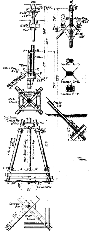 |
| Fig. 17. Detail of Mast: Sacramento River Crossing. |
 |
| Fig. 18. Details of Cable-Crossing at Bear River. |
At these three crossings the wires are not attached rigidly to the insulators, but are carried over wooden sheaves of 6 ins. diameter, made of lignum- vitae and grooved to fit the wire. The sheave has a steel shaft, each end of which is carried on one of the regular line insulators.
At a point near the Sacramento River it was necessary to support the line poles for a short distance upon piles driven 20 ft. into the ground. This was done as a protection against possible wash from the flood waters of the river.
THE CARQUINEZ STRAITS CROSSING.
Just before the combined waters of the Sacramento and San Joaquin Rivers enter San Francisco Bay, they pass through a narrow channel varying from half a mile to a mile in width and about five miles long. On both sides of the channel lie steep bluffs and hills, those on the south side being considerably higher than those on the north side. The channel is called the Straits of Carquinez, and is bordered by grain warehouses and the tracks of the Southern Pacific Railroad on the south side. Since the high voltage carried on the line prohibited a crossing below the water at that pressure, it became a question of either the Straits to first step down the voltage by transformers and then after its passage under the river, to step it up again; or to carry the wire across the Straits as an overhead crossing. The danger to cables lying in the bed of a swift river frequented by large ships, the cost of the transformer stations and the constant loss due to the two transformations led to the adoption of the overhead system, although there was no precedent for determining the behavior of cables of such a long span in a heavy wind.
The design of the cables was left to the John A. Roebling Sons Co., the primary condition being their electrical conductivity, since they were designed to carry the current and not to merely support a copper conductor. They were made of "plow steel," of a breaking strength of 192,000 lbs. per sq. in. As constructed, the cables are 7/8-in. diameter and are composed of nineteen strands of wire, with a total cross-section of 1/2 sq. in., making the breaking strength of the cable 96,000 lbs.
| |||
| Fig. 13. Saddle Insulators in Place on Tower. |
| |||
| Fig. 15. Strain Insulators in Cable Anchorage House. (Parts of Strain Insulator Shown at the Right. |
 |
| Fig. 19. Wire Entrances to Transformer Station at Carquinez Straits. |
Since the largest ships come up the river to the adjacent wharves to load wheat, it was necessary to provide a clearance of at least 200 ft. under the lowest wire. It was decided to adopt a safety factor of four in the cables when in a static condition, and with the above data, the curve of the cable was determined.
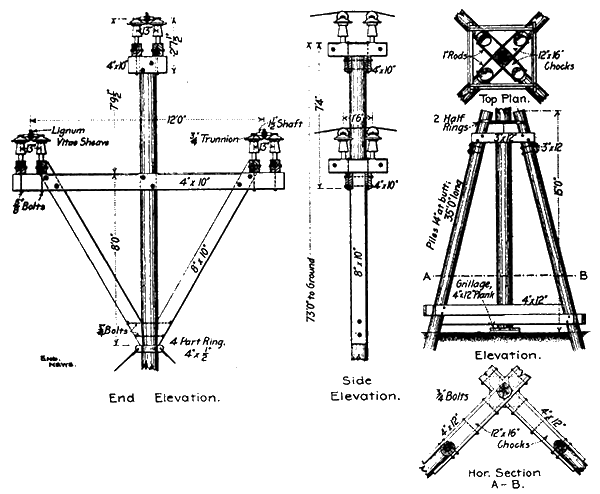
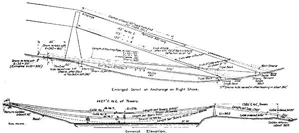
The problem of the design of the crossing, together with the towers, anchorages, etc., and the contract for the erection, was given to the Pacific Construction Co. , of San Francisco, of which Mr. F. A. Koeditz is engineer. After several surveys of various points, the crossing was located about one mile west of Port Costa.
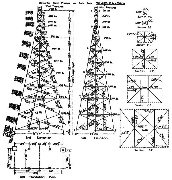
The general design is shown by the drawings. The main span of the cables is 4,427 ft., with a deflection of 227 ft. from the highest elevation. The lowest wire is 208 ft. above the water at the lowest point of the wire. On the north side a leaning tower was placed, as shown, in order to deflect the cables to the ground and to shorten the shore span. The cables pass over the towers on grooved rollers and the deflection angles are the same on both sides in order to give a vertical reaction. The cables, of which there are four, are 20 ft. apart horizontally, and on each side 20 ft. apart vertically. From one cable on one side of the tower to the nearest cable on the opposite side, there is a vertical distance of 10 ft. This arrangement was used in order to allow for considerable swing at the center of the cables without there being a possibility of contact. While but three cables were necessary, four were erected in order to have one in reserve.
 |
| Fig. 20. Sectional Elevation of Anchorage and Shelter for Carquinez Straits Cables. |
 |
| Fig. 21. Details of Saddle and Insulators for Carrying Cables on Towers. |
 |
| Fig.22. Details of Strain Insulator and Connections. |
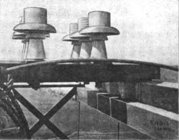
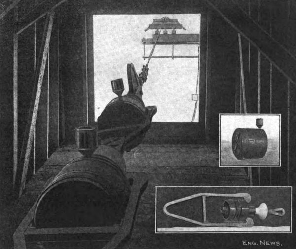
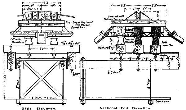
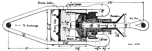
Each cable exerts a pull of about 24,000 lbs. on the anchorages, and since they carry the current, it was necessary to insulate them from the earth. The first strain insulators designed were of porcelain, of about the same shape as the micanite parts used in the ones adopted, but the manufacturer failed to turn out an article that would stand the physical test. Some that were tested broke on the first application of the testing machine. The insulators shown in the drawing were then designed, the essential insulating material being micanite, a preparation of sheet mica and shellac formed under hydraulic pressure. This was surrounded by an insulating oil in a copper tank. Two of these insulators are used at each anchorage for safety.
The cast-iron saddle which carries the cables rests upon a wooden platform covered with tarred canvas and provided with a gutter and spout. This platform, in turn, rests upon six porcelain insulators, with triple petticoats, the insulators being supported by steel pins passing through the timber supports. The whole is supported at a distance from the ironwork of the towers by wooden arms. A suspended platform is provided for inspection. These insulators under the saddles, together with the strain insulators, were designed for the purpose by Mr. R. H. Sterling, Superintendent of the Bay division.
The cables at the anchorages are provided with a long turnbuckle for adjustment, and a nest of steel springs to take up any sudden motion. The cable is attached to a large sheave at the outer end of the insulators, over which it passes, the end being bound to the cable with clips. The anchorage is a mass of concrete in which are embedded the necessary beams and rods.
The whole of the insulators and attachments are enclosed within a frame house, provided with a large plate-glass window in front, through which the cable passes by an opening 9 ins. in diameter.
 |
| Fig. 23. Strain Sheet for 224-Ft. Tower. |
The towers were built of steel throughout. The legs are of latticed channels and the bracing is of four angles latticed. Rods were used only in the horizontal bracing. The legs rest upon concrete blocks founded on the underlying rock. A ladder is provided on each tower. All ironwork was painted with silicon graphite paint and the timbers supporting the cables were oiled, filled and varnished with spar varnish.
Each of the cables were made in one length and arrived on a large reel. They were unloaded from the cars to a small wharf on the south side of the Straits. From there the end was drawn up the hill, over the south tower and fastened to the anchorage. The reel was then placed on a barge and towed across the river, the cable being allowed to sink to the bottom. The reel was landed on a small wharf on the other side, and the remaining portion of the cable was unreeled. A line was then passed over the tower and the cable was drawn to position by a hoisting engine stationed near the leaning tower. The arrangement of the blocks and engine are shown in the sketch. The four cables were placed in position in five days. The work of erection was under the direct charge of Mr. Frank Fields, general foreman, and Mr. Frank M. Butler, of the Pacific Construction Co., and was successfully carried out without mishap.
After erection, the cables were oiled with Lucol oil by a man in a traveling carriage. The carriage consisted of a platform 3½ x 5 ft. , hung from the cable by iron straps connected to two roller-bushed sheaves. The platform, which was hung 5 ft. below the cable, was provided with a railing. The whole was moved in and out by a man at the tower, who operated a windlass and line, the line being supported every 100 ft. by a traveling hanger.
It is of interest to note that the cables are practically stationary in the highest winds. No particular observations have been made under such circumstances, but with a wind of 25 miles an hour an oscillation of about 2 ft. and of long period can be observed from below. It is probable that the principal effect of the wind acting on the entire length of 4,427 ft. is to deflect the cable somewhat to one side. With the slight morning wind the cable is subject to considerable tremor and becomes charged with static electricity, but with the coming up of stronger winds, the tremor in the cable disappears.
THE TRANSFORMER STATIONS.
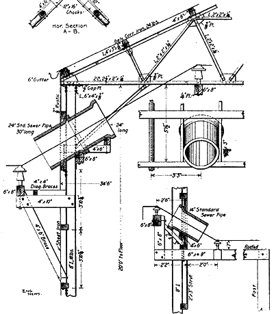
At the Oakland end of the line the transformers and generators were placed in the Piedmont Power Station of the Oakland Transit Co. At Carquinez Straits, a transformer station, 34 ft. 6 ins. x 55 ft., was erected on each side of the river, near the cable anchorages. The buildings are of steel frame, with timber purlins, and are covered with galvanized corrugated iron. On the roof a double layer of iron was laid 6 ins. apart vertically to prevent condensed water from dripping on the machinery. The floors are of wood in two layers. The only feature of particular interest in the design of these buildings was the method of introducing the high-tension wires. Two lengths of 24-in. standard salt glazed sewer pipe were framed into the walls on an incline; the inner end being covered with glass.
 |
| Fig. 24. Diagram Showing Arrangement of Tackle and Sheaves for Hoisting Car Quinez Cables. the Pacific Construction Co., Contractors. |
The equipment of these stations consists in each case of four 500 K-W. oil-insulated and water cooled Stanley transformers, one being in reserve. The line voltage is stepped down to 5,000 volts. The secondary current is distributed from a low-tension switchboard by means of two circuits at each station to the various towns within a radius of 5 or 6 miles. The most interesting details in these stations are the switches, designed to handle a pressure of 60,000 volts and a current of 25 amperes. They are a combination of switch and fuse, the fuse being mechanically released when it is desired to open one of them, and the arcing taking place at the end of the fuse. The igniting arresters are also contained in these building, besides the electrically-driven pumps for circulating the water in the transformers.
A plant for pumping water from the level of the railway tracks near the river has been installed and a 6-room cottage has been built for the accommodation of the station tenders.
The main office of the company is at 324 Pine St., San Francisco. Mr. Eugene J. de Sabla, Jr., is President and General Manager, and Mr. F. M. Ray, Assistant Manager. Mr. L. M. Hancock is General Superintendent of the company. Mr. T. E. Theberath is Superintendent of the Yuba division, Mr. Geo. Scarfe is Superintendent of the Nevada division, and Mr. R. H. Sterling is Superintendent of the Bay division, in which capacity he has had entire charge of the construction of the line from Wheatland to Oakland. The present writer had charge of the construction of the Carquinez Straits crossing for the company, and also designed the transformer station buildings and the crossings at the Bear and Sacramento Rivers.
