[Trade Journal]
Publication: The Central Station
New York, NY, United States
vol. 4, no. 8, p. 476-482, col. 1-2
The Gromo-Nembro Power Plant.
BY EMILE GUARINI
The three-phase 40,000-volt power-transmission from Gromo to Nembro (Lombardia) is stated to be the first plant of its kind in Europe. The power is taken from the Serio, which was found capable of developing 4,000 H.P. At present 2,000 H.P. have only been utilized at Gromo and transmitted by a three-phase overhead line to Nembro, some 35 kilometers distant, where the spinning mills of Messrs. Crespi & Co. have to be driven.
The high-pressure of 40,000 volts was chosen to dimension the line from the very beginning to transmit also the 2,000 remnant horse-power at a pressure of 40,000 volts.
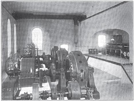
The central station has been built at the foot of the mountain on whose face the top part of the penstock has been laid. Three generators of 1,000 H.P. each direct coupled to Escher-Wyss turbines by means of Zodel couplings are placed in a row. Behind the generating sets two exciters, also direct driven by water wheels and each having a capacity of 25 K.W., have been put down. These machines are provided by Messrs. Brown-Bovery & Co., Baden.
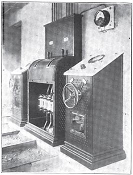
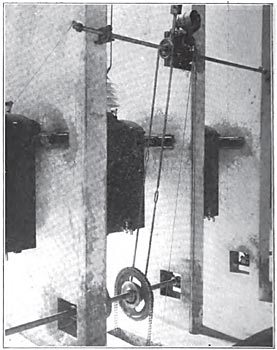
| |||
| Direct Connected Generators and the Operating Board at Gromo. |
The transformer station is situated at Nembro, in close proximity to the factory. This station contains only two 500 K.W. transformers, designed for a normal continuous output of 500 K.W., the ratio of transformation being 38,000-500 volts.
The connections in the generating station have been arranged with a view to securing the maximum simplicity. Each generator works directly onto the primary of an Sso-K.W.A. stationary transformer. The total power leaves the secondary terminals at a pressure of 40,000 volts and is then led to the high pressure bus-bars, in order to allow of parallel running with the other units. By eliminating the bus-bars between generators and transformers, the number of controlling and measuring apparatus is practically halved. The transformers for meters and the overload relays are energized from the 4,000-volt side.
The generators are of the horizontal shaft type, with stationary star connected armature and revolving field magnet. Each machine has a normal continuous output of 1,000 H.P. on a power factory of 80 per cent. at a pressure of 4,000 volts. The machines are 12-pole, and run at a speed of 500 r.p.m. and have a freezing of 50 cycles per second. The efficiency, including excitation losses, was 93 per cent. at full load, and 89.5 per cent. at half-load. The drop of voltage from no load to full load was found to be, on a power factor of unity, 7 per cent., and on a power factor of 0.80, 20 per cent. The magnet wheel, poles, and pole shoes form one steel casting. The armature coils are former wound. The weight of the complete machine amounts to 13 metric tons, being 13 Kg. per B.H.P.
Each exciter is capable of developing 25 K.W., 217 amperes at 115 volts when running at a speed of 800 r.p.m. These dynamos have six poles, the later being built up of soft-iron laminations. The dynamo frame is of the best cast-steel. The armature is of the slotted drum type. The guaranteed efficiency for these sets was 89 p.c. at full load, and 87.5 p.c. at half load.
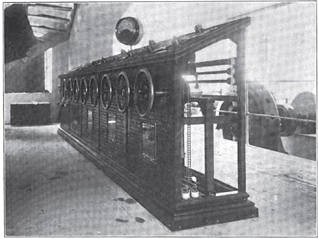
| |||
| Main Operating Board in the Central Station at Gromo. |
The transformers are designed each to give an output of 890 K.V.A. when working on a 50-cycle circuit, the ratio of transformation being 4,000:40,000. The efficiency obtained on a non-induction load was 97.8 p.c., as against 97 p.c., the guaranteed figure; the inherent regulation, i.e., the drop of voltage from no load to full load, and non-inductive load was 0.76 p.c., and with power factor 0.7, it was 2.6 per cent. These apparatus withstood a flash test of 67,000 volts applied between primary and secondary windings. The overall dimensions of the transformers are as follows: Length, 1600 mm.; breadth, 1,360 mm.; height, 2,180 mm. These transformers are of the oil-insulated and water-cooled type, the average quantity of water required per minute being 18 litres. Each transformer consists of three vertical limbs placed in the same plane, and held firmly together at both extremities by means of soft-iron yokes. The primary and secondary windings are wound in the shape of concentric cylinders, and are separated from one another by means of a strong insulating partition. The high-pressure coil is wound in sections. Each subdivision has potential difference of only 300 volts between its terminals.
The transformers at Nembro station are of the same type and design as those at Gromo. The efficiency obtained on non-inductive full load was 97.6 per cent., which compares favorably with 96.8 per cent., the guaranteed figure. The inherent regulation on non-inductive full-load was 0.8 per cent., and with power factor 0.70 was 2.9 per cent. The insulation between primary and secondary coils withstood a pressure test of 57,000 volts. The overall dimensions of these transformers are: Length, 1,600 mm.; breadth, 1,155 mm.; height, 2,005 mm. These apparatus take 13 litres of water per minute each for cooling purposes.
The switch gears have been designed with exceedingly great care. At Gromo, all the switch gear, together with the transformers, is erected in a special building adjoining the engine room. The switch house consists of a basement and three stories. The basement is divided into two compartments. The first one contains the regulating resistances and frame work for the 4,000 volt apparatus; the second compartment is situated 2.7 above the engine house floor, and holds the transformers. The leads from the engine room reach the first compartment through a wide trench provided under the engine room floor. The first floor is also subdivided into two rooms; one gives access to the engine room, forming a kind of gallery whence the whole of the installation can be surveyed. This compartment contains the main operating board with the switch handwheels and measuring instruments. In the second room the high-tension automatic switches, together with the three current transformers for the outgoing feeder, are erected. The conductors and leads are all placed in one common trench under the engine room floor, which leads into the basement. The second floor has been entirely taken up by the omnibus-bars, and the pressure transformers connected therewith. The third floor has been reserved for the lightning arresters and the leading-out arrangements of the line.
| |||
| Front View. 40,000 Volt Oil Switches. |
The transformer station at Nembro is a plain two-storied building. Both floors are subdivided each into two compartments. On the ground floor at the back the transformers are situated; in the front room, mounted on the separating wall, are the secondary bus-bars with the disconnecting gear and current transformers. Immediately above the transformers on the next floor are the high-pressure automatic switches; these are identically the same both as regards construction and modus operandi as those installed at Gromo, which will be described. In the first room there are two desk type panels for the high-tension oil switches and a distributing panel for the 500-volt feeders. The latter carries two 500-volt switches. On the second floor the 38,000 volt bus-bars have been placed. These are duplicates of those erected at Gromo. The lightning arresters are placed in the next compartment together with the leading-in arrangements.
| |||
| Back View. 40,000 Volt Oil Switches. |
At Gromo, each generator has its own framework for carrying the following apparatus: Three H. T. single-pole removable tube type fuses with blow-out horn, one pressure transformer with fuses, and two current transformers. The framework is a riveted structure made completely of iron. The leads enter the transformer room through thick glass tubes cemented into the dividing wall. In laying out the 40,000-apparatus, the extra H. T. bus-bars were taken as the starting point. In order to exclude all possibility of arcs being formed between bars of different polarities, each phase was enclosed in a separate cell made of incombustible material. Great care was taken in obtaining a mechanically strong and at the same time electrically efficient insulator. This insulator consists of three parts, glazed separately but baked together. The main body of the insulator has four deep grooves. Each insulator has to withstand a test of 100,000 volts before being delivered. Immediately below the extra high-pressure equipped with a separate switch. The three elements are, however, operated simultaneously. A similar structure was adopted for carrying the switches as for the bus-bars, and each switch is separated from its neighbors by a wall of 120 mm. thickness. In this way each switch is placed in a fireproof cell of 600 mm. width. Through an aperture at the top, the connections pass from the switches to the bus-bars. Removable disconnectors have also been provided, which permit one to isolate any of the cells when the same have to be switched out of circuit to be cleaned or inspected.
The disconnectors are composed of copper strips with stop split-pins. These copper strips fit into two contacts mounted on porcelain insulators. They are handled by means of a wooden rod provided with an insulator at its extremity. To further safeguard the attendance, the bush, by means of which the insulator is fastened on the stick is earthed through a little metal chain; this enables the attendant to operate the disconnectors, when the switches are open, without running any risk. The switches embody all the main features of the Brown-Boveri oil switch, but as they are adapted for 40,000 volts they possess some interesting features. The switch is operated from a distance by means of the hand wheel on the main board, and is actuated by a rotary motion. The latter is probably the most suitable mechanical movement for appliances of this kind, a great advantage being that one is not tied down to a particular spot for placing the switch, for, by means of a countershaft the apparatus can be controlled at almost any distance. The switches are of the multiple break type. Both the moving and the stationary contacts, as well as the mechanism, are immersed in an oil bath, so that nothing appears above the surface of the oil but insulating material and the earthed parts of the apparatus.
The oil reservoirs are quickly lowered to give access to the contacts. To avoid fusing of the main contacts, small auxiliary ones have been provided, which carry the current at the moment of breaking the circuit. These contacts are easily renewable. To make sure that the spark produced when breaking the circuit is quickly destroyed, the contacts have been formed in such a way that, at the moment of rupture, a volume of oil is forcibly thrown against them. In order to weaken the destructive effect of the spark the circuit is simultaneously broken in six places. By doing away with this, a small travel for the moving contacts can be allowed. This travel, in the present case, amounts to 8 cm., thus giving an effective oil-break of 35 cm., after having subtracted the overlap of the contacts. This break ought to be sufficient even for a pressure of 40,000 volts. Moreover, in three-phase working, two phases have to be considered as forming one circuit, thus giving twelve simultaneous interruptions per phase. This switch is composed of three single-pole elements combined into one apparatus, the oil-baths being kept separate. On turning the switch hand-wheel the rotary movement is transmitted to the switch spindle, which, in its turn, actuates a crank. The latter moves the contacts and closes the circuit, and also puts under tension the springs fixed around the guides. If by mistake the crank is turned past the dead point, the switch will, nevertheless, remain closed. When the switch is worked automatically, on the contrary, the crank never quite reaches the dead point, but is kept in position by means of a pawl and a cam wheel. As soon as the pawl is lifted, the springs of the switch pull the contacts apart. In the smaller type of switches the catch is influenced directly by an electromagnet. For larger types, when, for instance, three switches have to be released at the same time, a common release spindle is provided, and the break is effected by the falling of a weight. The position of the weight in its turn is controlled by an electromagnet. When the switch is closed, the weight assumes its original position. A driving shaft, common to the three switches, is supported in bearings fixed in the walls, and operates the switch spindles through a chain drive. The switch hand-wheels on the main board impart motion to this shaft also through a chain drive. The driving gear has to be turned to "off," as soon as a circuit has been closed. In order to effect this, the chain wheel of the driving shaft is not keyed but runs loose on the latter. A pin projects from one side of this wheel, and travels in a semi-circular slot cut into the side of the little rope pulley keyed onto the driving spindle. When turning the chain-wheel clockwise, i.e., when closing the switch, the projecting pin engages the pulley, and the movement is transmitted to the driving spindle. When the chain-wheel revolves in the opposite direction, the stop turns idly round in the semicircular slot of the rope pulley. By means of a catgut rope running over the pulley, and another pulley fixed on the spindle of the switch handwheel, a pointer is made to indicate the exact position of the contacts at any moment.
The generator board is built in the form of a desk, the top part inclining towards the operator. The operating board is only equipped with low pressure apparatus, and consists of three generator panels, one feeder panel and one exciter panel.
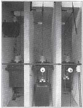
| |||
| Lightning Arresters. |
The lightning arresters are of the well-known Wurtz type and are insulated from earth by several porcelain insulators. On a level with the lightning arresters are the leading-out arrangements for the high-pressure line. Each line leaves the power house through one of the glass panes of the window. On both sides of this glass pane a stout glass tube projects, through which the conductor leaves the building.
The connections of the Nembro substation, as far as high-pressure circuits are concerned, are similar to those of the Gromo station. A three-pole emergency switch mounted on poles outside the station allows of the complete isolation of the substation. The switch is of the well-known horn break type. To avoid sparking which could happen through the presence of a foreign body between the horns, etc., three contacts have been fixed to the switch which, when the same is opened, short-circuit the lines entering the station and connect them to earth.
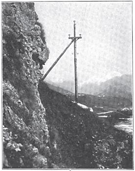
| |||
| Pole Line of the Gromo-Nembro Plant. |
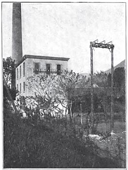
| |||
| Substation at Nembro. |
The desk panels at Nembro are the exact reproduction of the Gromo board, except that only one hand-wheel has been provided.
The line enters the substation in identically the same way as it leaves the primary station at Gromo, and the current passes through the lightning arresters to the H.-T. bus-bars. The leads pass through three single pole automatic H.-T. oil switches to the primary windings of the transformers, the secondary being again provided with three-pole disconnectors and two-current transformers, one for feeding the overload relay and the ammeter, the other for the relay only. The transformers feed the L. T. bus-bars at 500 v. These buses are connected with two-feeder circuits for supplying the motors, etc. Each feeder circuit is provided with a switch and the necessary fuses.
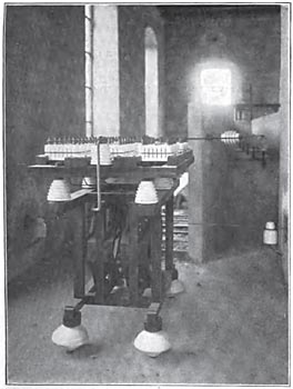
| |||
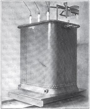
| 600 K. W. Transformers at Nembro. |
The total length of the overhead line is approximately 32 km.; the line has been calculated to transmit a total of 4,000 horse-power with a drop not exceeding 5 per cent. The line consists of three highly conducting bare copper wires of 6.5 mm. diameters each mounted on Delta insulators specially designed for this installation. The insulators are fixed on wooden poles and cross-arms. As a rule, the lines are mounted on a single pole, in the form of a triangle, with 850 mm. side. Where long spans and sharp bends occur, two poles have been erected and the insulators mounted on the cross beam at a distance of 1,000 mm. from center to center. The longest span is 120 m. and the sharpest angle 145°. The standard height of pole is 8 meters above the ground, or 9 m. at crossings, the lower insulators being placed at a height of 7.5 m. above the ground. A telephone line connecting the central station with the substation is fixed on the same poles at a distance of 1.5 m. below the high-pressure main line. This line consists of two silicon bronze wires of 3 mm. diameter each, mounted on ordinary insulators. Each high-tension insulator had to pass a flash test of 80,000 volts without showing signs of breaking down.
| |||
| Low Pressure Bus-Bars at Nembro. |
| |||
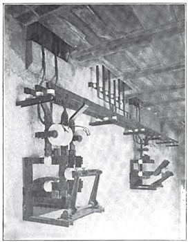
| Controllers in Nembro Substation. |