[Trade Journal]
Publication: Electrical World
New York, NY, United States
vol. 47, no. 8, p. 405-406, col. 1-2
The District Supply System of the North
Shore Electric Company, Near Chicago.
IN the summer of 1902 Mr. Samuel Insull, president of the Chicago Edison Company, began the acquisition of the various electrical plants operating in the suburbs of Chicago, having in mind their consolidation under one management and the generating of the necessary current in stations of sufficient size to operate economically.
The company organized to carry on this work is known as the North Shore Electric Company and has the following officers: Mr. Frank J. Baker, vice-president and general manager ; Mr. F. W. Insull, secretary and treasurer, and Mr. George H. Lukes, general superintendent.
Originally controlling a small part of the north shore suburban territory, the company has extended until now it owns the largest system of district, or village to village, electrical distribution in the Middle West. It controls practically all the suburban lighting around Chicago, and by so doing has made it possible to supply electric light and power to a number of small suburban towns where a purely local plant would not have been able to operate profitably.
As the suburban territory around Chicago is certain to have a large and rapid growth, high standards of construction have been adhered to; much higher, in fact, than would be justified in rural communities where no such rapid growth is sure to take place. The general engineering methods are naturally those of the Chicago Edison and the Commonwealth Electric Companies operating in Chicago, of which Mr. Insull is president, but of course many modifications have been introduced in these methods to suit them to suburban work where the load is more scattered than in the city.
 |
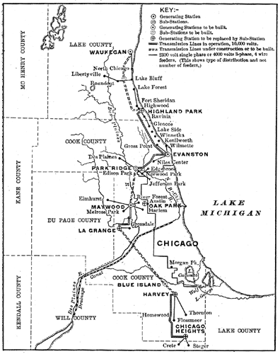
| Fig. 1. — Map of North Shore Electric Company's System. |
The extent of the company's system can be seen by the map, Fig. 1, which shows in diagram the location of this company's generating stations, sub-stations and transmission lines. It will be seen that the company's distributing systems extend from Waukegan, 37 miles north of the business district of Chicago, to Chicago Heights and Crete, about 30 miles south. The general plan adopted has been to transmit from toe generating stations to substations over three-phase, 60-cycle, 10,000-volt, high-tension lines. These high-tension lines have been constructed with the intention of raising the voltage to 20,000 when the load increases enough to necessitate it. At the various sub-stations static transformers are placed, which step-down from 10,000 to 2,300 volts. The local distribution from each sub-station is by means of a 2,300-volt, four-wire, three-phase, 60-cycle system. By this system the secondaries of the sub-station transformers are Y-connected. Between the neutral point and the outer wires 2,300 volts is obtained, and between any two outer wires 4,000 volts. This gives a three-phase circuit at 4,000 volts for power purposes and 2,300-volt, single-phase circuits for lighting distribution.
Referring again to the map, Fig. 1, and beginning at the extreme north, it is seen that a generating station is located at Waukegan. The Waukegan station supplies by ordinary 2,300-volt distribution the towns of North Chicago, Lake Bluff, Rondout and Libertyville, taking a maximum or peak load of about 400 kw. At Highland Park is another generating station, the peak load upon which is about 475 kw. This supplies Highland Park, Lake Forest, Fort Sheridan, Highwood, Ravinia and Glencoe. This station is connected by a transmission line to a generating station at Evanston. The Highland Park station is operated only during part of the day, and it is the intention to do away with the operation of the steam plant there and make it purely a sub-station as soon as possible. The company finds that stations operated to carry a peak load only are expensive luxuries and to be avoided as far as possible, although it is well to keep the steam machinery as a reserve for use in case of breakdown. At Evanston the company has two plants, from one of which hot water heating is supplied. These two plants carry a peak load of 800 kw and supply Evanston, Wilmette, Gross Point and Niles Center by a 2,300-volt distribution. The Evanston stations carry all of the load at Highland Park except during the peak. It is proposed to build a transmission line from Highland Park to Waukegan and to erect a large economical generating station on the lake shore at Waukegan. Thus the Waukegan and Evanston plants will be connected by transmission lines and it will be possible to carry much of the load of the north shore suburbs from the Waukegan plant, although on account of the hot water heating business in Evanston and the large load there, the generating stations in Evanston cannot be abandoned.
From Evanston a transmission line runs to a sub-station at Park Ridge, upon which there is a maximum load of 150 kw. From this sub-station the suburbs of Des Plaines, Park Ridge, Edison Park, Norwood Park, Jefferson Park and Edgebrook are supplied.
The next generating station is at Maywood, where a new plant is being erected, as it is in the center of the important suburban district directly west of Chicago. The transmission line will soon be completed between Maywood and the Park Ridge sub-station, thus connecting Maywood with Evanston. The Maywood station supplies Maywood, River Forest, Harlem, Melrose Park and Elmhurst, all by 2,300-volt distribution except the line to Elmhurst, which is operated at 5,000 volts with step-down transformers at Elmhurst, reducing to 2.300 volts. The street lighting at Elmhurst is by 32-cp incandescent lamps supplied from a low-tension, multiple distribution, the street lighting transmission line being switched on and off at the power station at Maywood. The peak load on Maywood is about 250 kw, but this does not include the power to be supplied from there over the transmission line to La Grange.
From Maywood to La Grange is a 10,000-volt transmission line, recently constructed for the purpose of making it possible to shut down the steam plant of the La Grange Service Company and operate it as a sub-station. This is another combined water and lighting plant. Centrifugal pumps with vertical shafts built by the Byron-Jackson Machine Works in San Francisco will be used for this pumping. These pumps have been extensively used for the pumping of irrigation water and in mines, operating against very high heads, in California. The peak load at La Grange is about 250 kw. From this sub-station La Grange, La Grange Park, Grossdale and West Grossdale are supplied by 2,300-volt lines. From La Grange to Blue Island there is a long stretch of country containing no suburban towns of much consequence. Probably some day a transmission line will be built connecting the southern suburbs with La Grange.
At the present time there is a combined electric light and water pumping plant at Harvey and an electric light plant at Chicago Heights. These two towns are connected by a transmission line and one or both stations operated as suits the company's convenience. The heaviest load is at Chicago Heights, but it is necessary to operate the Harvey steam plant continuously at present on account of the water pumping. It is now proposed to build a steam plant at Blue Island on the Calumet River. This will be a steam turbine condensing plant of good size, for supplying Chicago Heights and Harvey, and also furnishing energy to the Chicago & Southern Traction Company, which now controls the electric railway line from Harvey to Sixty-third Street, Chicago, and is constructing south from Harvey through Chicago Heights to Kankakee. From Harvey the towns of Thornton, Homewood and Flossmoor are supplied at 2,300 volts, and from Chicago Heights 2,300-volt lines are run to Steger and Crete. The peak load at Harvey is 150 kw, and that at Chicago Heights 400 kw. From this map and description it is seen that the company supplies a very large territory, and that when the transmission lines which it is proposed to construct immediately are completed, the generating stations will be so interconnected that the load can be distributed between them in an economical manner, and the possibilities of interruption to service reduced to a minimum.
 |
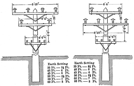
Fig. 2 shows the standard pole line construction used for the high-tension lines connecting generating and sub-stations. As before explained, these lines are now operated at 10,000 volts with the idea of increasing this voltage ultimately to 20,000 volts. As all the details of construction are specified on the drawing, very little explanation is necessary. The insulators are porcelain, Locke No. 408A, on the line which is now being constructed. These are larger than many that are commonly used on 20,000-volt lines, so that there is a good factor of safety. The lower cross arm carries four telephone wires. Although these pole lines are constructed for two transmission circuits, only one circuit has been placed on any of them so far. The ordinary length of pole in the country is 40 ft. This length is, of course, varied to suit conditions. Thirty-five-ft. poles would do ordinarily in the country but for the fact that most of the company's transmission lines have also 2,300-volt distributing circuits on lower cross arms. The smallest wire that will be used on transmission lines in the future is No. 3 hard-drawn copper, this minimum size being used to secure mechanical strength. The telephone lines are No. 12 hard-drawn copper.
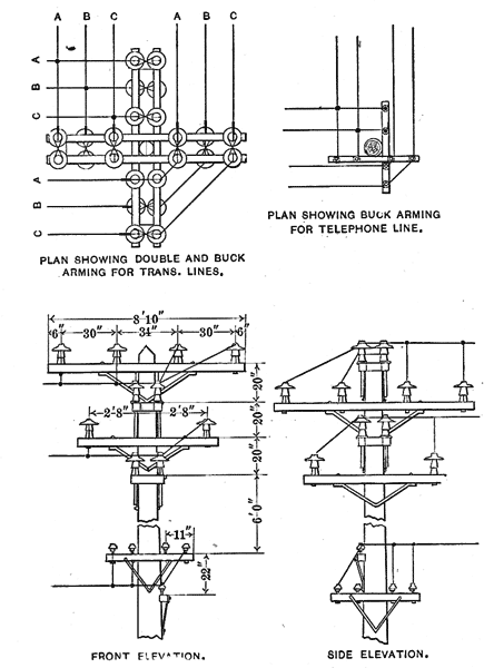
Fig. 3 shows the standard transmission line construction at a transposition. The telephone line is transposed every five poles on Locke No. 7 insulators.
 |
| Fig. 4. — Diagrams of Corner Poles. |
Fig. 4 shows the standard construction at corners for the transmission and telephone lines.
The present lines are mainly located on highways for which franchises had to be secured as well as the consent of the property owners along the route. In a few places the company has purchased consent to set poles on private property. After considerable experience with the right-of-way question, the company has come to the conclusion that in general it is better to secure private right-of-way, rather than build on the highway.
The general plan of operation is to keep the 2,300-volt bus-bar voltage constant at the sub-stations and to regulate the various single-phase lighting feeders with C. R. regulators, by which the voltage can be raised or lowered to per cent.
No fuses are used in the 2,300-volt distributing circuits save at the transformer terminals. Automatic circuit-breakers are provided on feeders at sub-stations. No time limits are placed on automatic circuit-breakers at sub-stations, but a time limit device is used on those at generating stations so as to give the circuit-breaker on any feeder time, to act before that at the generating station will open and so prevent opening the station circuit-breaker in case of a heavy short-circuit on one feeder. The switch used on all 4,000-2,300-volt circuits is the type K3 oil switch of the General Electric Company.
The 10,000-volt transmission lines outgoing from power stations have General Electric type H3 switches and the incoming 10,000-volt lines at sub-stations have General Electric K6 switches.
Most of the sub-stations are of sufficient importance to justify the keeping of men on duty there twenty-four hours per day. The Park Ridge sub-station, however, which supplies a number of very small suburban towns, has an attendant only during the night when current is on. At present the company gives twenty-four-hour service in most of its territory. As soon as plans are complete, it will do so throughout all of it. The company maintains district offices at or near its stations and sub-stations. In small villages where there is no sub-station, arrangements for lamp renewals, etc., are made with some village store. Free lamp renewals are given. In Evanston and Waukegan, the two largest towns in the company's territory, a delivery service for lamps is maintained, although in some places an extra charge is made for the delivery of lamps. As indicated by Mr. Baker, the vice-president, in a discussion at the last Illinois State Electric Association, the company finds that the policy of furnishing free lamp renewals is desirable in order to make sure that the customer's sockets are not filled with low-efficiency lamps purchased at Chicago department stores, and that the customer's do not neglect to renew burned-out lamps and so cause a loss of revenue to the company.
The company has its own telephone lines, carried on the transmission lines as indicated. Special attention has been given to the protection of telephone instruments, and a special cut-out with a very long enclosed fuse of No. 40 wire is used in each telephone circuit where it enters a building.
