[Trade Journal]
Publication: Electrical World
New York, NY, United States
vol. 47, no. 16, p. 819-822, col. 1-2
Hydroelectric Development in the Adirondacks.
RAQUETTE RIVER falls 385 ft. along its course of five miles below Colton Village. N. Y.. and at the foot of this descent the combined electric power house and pulp mill of the Hannawa Falls Water Power Company is located. At this power house spruce logs are ground into wood pulp, and electric energy is developed for transmission to Ogdensburg and other points more than thirty miles distant. When the water is not wanted to drive the electric generators, it is turned into the wheels that operate the pulp grinders, and the problem of a variable load factor is solved.
The importance of this plan for the double use of water power may be gathered from the fact that the power house named is designed to utilize 84 ft. of the fall in the river, that the rate of river discharge sometimes falls as low as 1,000 cu. ft. of water per second, and that the total rating of turbine wheels used to operate the electric generators and pulp making machinery is fully twice as great as the net power that this quantity of water will develop. Managers of electric power stations in regions where wood pulp can be made to advantage may perhaps draw a valuable lesson from this example.
| |||
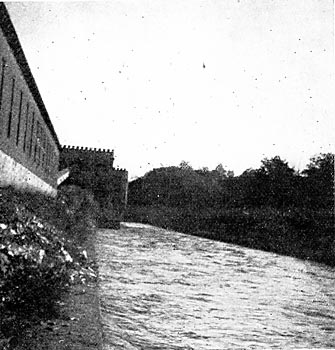
| Fig. 1. Tailrace. |
Above the darn at Hannawa Falls, the drainage area of the Raquette River is 953 square miles, and most of this lies in the great lake and swamp region of the Adirondack Mountains, at elevations of 1,000 to 1,700 ft. above sea level. In this region and forming a great storage reservoir from which the Raquette River flows, arc the Tupper lakes, Long Lake, Raquette Lake. Brandreth Lake, and a score or more of small lakes and ponds.
Having left this region of swamps, lakes and mountains some miles behind, the Raquette River reaches the head of the great falls at Colton with a surface elevation of 800 ft. above sea level, and from this point its descent of 385 ft. in five miles begins. Along this part of the Raquette the water rights have been acquired by the Hannawa Falls Water Power Co., but only the lower 85 ft. of the total fall in this five miles of the river has thus far been developed.
| |||
| Fig. 2. Forebay, Penstock and Power House. |
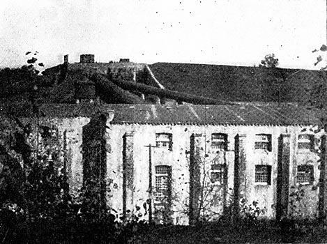
The present hydraulic development begins with a dam at the village of Hannawa Falls, which sets the water back for a distance of 2.5 miles, and forms a pond with an area of about 200 acres. From this dam a canal some 2.700 ft. long carries the water down stream to a forebay above the power house on the river bank. The head wall of this forebay is pierced by four steel penstocks that run underneath the power house, and rise to its several sets of turbine wheels.
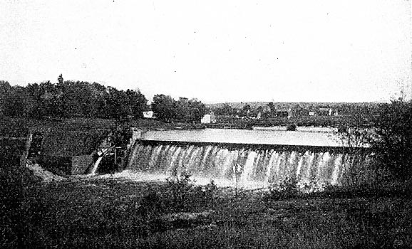
At Hannawa Falls, the darn across the Raquette River is built where the bed and perpendicular banks were of sandstone, and the distance between the latter was about 375 ft. Between its main abutments or wing walls the river section of the darn is 258 ft. long and rises to a maximum height of 40 ft. above the bedrock. Of this river section of the dam, a length of 234-1/2 ft. forms the overflow portion, 8 ft. are taken up by an abutment at one end of a waste gate, and the opening of this gate is 55.5 feet wide.
Adjoining the main abutment that supports one end of the waste gate is the entrance to the canal, 80 ft. in the clear, which is spanned by a stone bridge of five arches with four piers, each 4 ft. thick, underneath. The combined width of these openings between the piers and abutments at the head of the canal is thus 66 ft., and the standard width of the canal below its head is 30 ft. at the bottom and 110 ft. at the top, with side slopes of two to one. From the top of its banks to its bottom the canal is 20 ft. deep, and the bottom is 54 ft. below the crest of the overflow section of the dam.
| |||
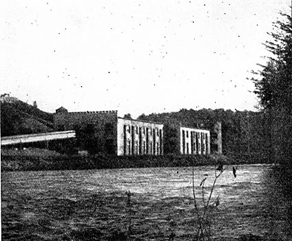
| Fig. 3. Power House and Pulp Mill. |
A few feet below the entrance to the canal there is a waste gate and weir, by which the water may be discharged into the river. The 15.5-ft. opening in the river section of the dam is closed by four steel waste gates set in a steel frame, and the sill of this frame is 30 ft. below the crest of the dam. Each of the four gates measures 6 by 8 ft., two of the gates being at the bottom and two at the top of the opening. The two lower gates are operated by hydraulic cylinders, and the two upper gates are opened by lowering them, so that any desired depth of water may flow over their tops. These large gates were made desirable by the necessity of providing for the passage of logs down stream, and for the purpose of controlling the level of water in the pond.
Beneath the dam very little excavation was necessary, as the beds of sandstone have a large dip down stream, and thus presented a toothed surface of excellent character for a foundation. The thickness of the dam at its base is 25 ft., and a little below the crest it is 7 ft. From base to crest- the dam consists of Potsdam red sandstone and cement. On the upstream and downstream faces of the dam a rubble wall at least 3 ft. thick was laid and between these walls the center of the dam was filled with large irregular pieces of sandstone packed with cement concrete. On the downstream side the stones in the dam are laid in Portland cement, and for the remainder of its masonry natural cement was used. The concrete used in the center of the dam was composed of one part natural cement, two parts sand, and four parts broken sandstone.
At its head the canal may be closed by means of stop-gates between the stone piers named above. From these gates to the forebay, on the high bank above the power house, the length of the canal is about 27 ft., and it is designed to deliver 2.500 cu. ft. of water per second, at a velocity of 3 ft. per second. It is expected that when storage reservoirs at the head of the Raquette have been constructed, the river will have a constant discharge of not less than 2,500 cu. ft. per second.
 |
| Fig. 4. Elevation of Power House, Storehouse and Pulp Conveyor. |
 |
| Fig. 5. Cross-Section of Power House Along Penstock No. 2. |
In its general course the canal follows the river, and lies partly in excavation and partly in embankment, with a bed of gravelly loam, sandstone chips, sand and clay. These materials have been so compacted that the canal shows no leakage. At the forebay and along 50 ft. of the canal above it, the bottom is formed with a layer of concrete in which expanded metal is embedded. Beneath this layer of concrete, which is 4 in. thick, there is a layer of clay that has been packed with water, in the forebay. Retaining walls of masonry support the ends of the canal banks at the forebay, and connect with the forebay head walls that receive the steel penstocks. From these retaining walls, core walls of masonry run back some 50 ft. into the banks. The head wall of the forebay is built with two faces that unite at a large angle, and one of these faces receives three and the other four, steel penstocks. Concrete with embedded sandstone forms the basis of these forebay walls, their outside is faced with sandstone blocks, and between each two penstocks there is a buttress of stone masonry 4 ft. wide and 2 ft. thick.
 |
| Fig. 6. Plan of Lower Floor of Power House and Pulp Mill, Showing Also Penstocks and Forebay. |
At the corners of the buttresses 6-in. x 6-in. angle irons are secured, and serve as guides for the head gates. These gates are of wood and are operated by racks and pinions that connect with a common main shaft driven by an electric motor. In front of the head gates is a steel rack, and all are covered by a wooden building. One of the seven penstocks is 6 ft. in diameter, and each of the others is 10 ft., and all are spaced with 18 ft. between centers where they enter the head wall. Each of the 10-ft. penstocks is enlarged to 12 ft. along 4 ft. at its upper end. Thus far the 6-ft. penstocks and three of the 10-ft. penstocks have been erected and connected with water wheels in the power house and pulp mill, but the heads of the three other 10-ft. penstocks are set in the forebay wall.
From the forebay to the turbine wheels each of the penstocks has a length of about 200zoo ft. At the site of the electric station and pulp mill the surface of the Raquette River is about 75 ft. below the crest of the darn. To take advantage of this condition, a tailrace was excavated from the electric station to a point about 1,100 ft. down stream, and this gives a tailwater level at the station that is about 9 ft. lower than that of the river, just outside of the tailrace wall.
The electric generating station is located over the tailrace, and at the foot of the high bank that carries the forebay.
At its first floor level the station is 72 ft. below the crest of the dam, and 12 ft. above the water level of the tailraces, so that the head on the turbine wheels is 84 ft. The building in which the generating equipment is located measures 250 ft. in length, 60 ft. in width along one-half of this length, and 75 ft. in width for the other 125 ft. The building is two stories in height. Its walls are of Potsdam red sandstone, its floors of concrete with expanded metal, and its roof of sandstone flags, two inches thick and laid on T irons. That part of the building which is 75 ft. wide, being the up-stream end, contains the electric generating equipment on the first floor. Across the upper end of the building a space 12 ft. wide, and including the tower, is separated from the remainder by a sandstone wall, and used for offices.
The generator room, where the water wheels and dynamos are located, is 115 ft. long, 75 ft. wide, and 22 ft. from floor to ceiling. Over the central part of this floor space travels a hand crane of 48-ft. span and 16 tons capacity, supported by steel columns. All of the second floor of the power house except the office space, and the down-stream half of the first floor, are occupied by machinery for the production of ground wood pulp.
Beneath the floor of the generator room the bedrock is distant some 21 ft., and over this the tail water is 9 ft. deep. Into this space between the station floor and the bedrock of the tailrace come one penstock of 6 ft. diameter and one of 10 ft. diameter, from the forebay above the high bank. The 6-ft. penstock rises to the case of a pair of Samson type, outward-discharge turbine wheels mounted on a horizontal shaft and located on the floor of the generator room. Under the working head of 84 ft. of water this pair of wheels operates at a speed which is regulated at about 300 revolutions per minute by a Lombard governor geared to the gate rigging. To each end of the shaft of this pair of turbine wheels a 350-kw, three-phase, 4,400-volt alternator is direct connected. For the pair of wheels the rating is 1,250 horse-power, and the combined rating of the two connected generators is 700 kw., on about 930 hp. The pair of generators just named have been in use several years for the supply of electricity to lamps and motors about Potsdam.
Along that side of the generator room which is nearer to the forebay runs a switchboard gallery 12 ft. wide, and beneath this gallery the transformers for the 201,000-volt transmission line to Ogdensburg and other points are located. The other steel penstock that runs beneath the floor of the generator room has a diameter of 10 ft., and its connections rise to three pairs of horizontal turbine wheels with a rating of 1,500 hp each. One pair of these turbines is belted to an exciting dynamo and an air compressor, and to pulp making machinery on the second floor. Each of the other two pairs of turbine wheels is direct connected to a pair of 350-kw, 4,400-volt, three-phase, 60-cycle General Electric alternators, which have just been installed.
From the 4,400-volt alternators the current goes in part to the transformers beneath the switchboard that raise the pressure to 20,000 volts for the transmission to Ogdensburg and Gouverneur. A part of the energy is transmitted at the generator voltage to Potsdam.
On leaving the water power station at Hannawa Falls, the 20,000-volt transmission line crosses the Raquette River, which is some 240 ft. wide at this point. The line then runs to Canton village, a distance of 10.5 miles, and on thence to the city of Ogdensburg, over an additional distance of 19 miles, so that the total length of the transmission in this direction is 29.5 miles. At a distance of about six miles from Hannawa Falls, a branch from the transmission line goes to Gouverneur village, which is some 25 miles from the junction point, so that the length of line from the water power station to this village is nearly 31 miles.
The line to Ogdensburg is now completed, and the branch to Gouverneur is under construction. On the run to Ogdensburg the transmission line is made up of two three-phase circuits on the same line of poles. Each circuit has three aluminum conductors formed individually of seven strands of No. 8 B. & S. gauge wire.
| |||
| Fig. 7. 20,000-Volt Line Hannawa Falls to Ogdensburg. |
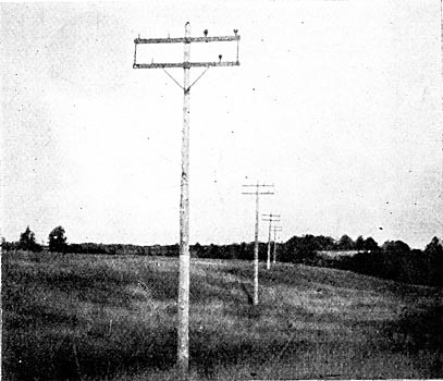
The cables are mounted on Locke porcelain insulators, each of which has three petticoats, is 5-1/8 in. high, and has a maximum diameter of 5.75 inches. From the plane of the highest to that of the lowest petticoat the distance is 2.5 in., and the diameter of this lowest petticoat is 2.75 inches. These insulators are mounted on locust pins of 1 7/16 in. diameter in the shank, that have been boiled in paraffin.
Cedar poles with not less than 8-in. tops and 12-in. butts are used for the 20,000-volt line. Each pole carries two crossarms set with centers 23 in. apart, the upper arm having its center 10 in. from the top of the pole. Each arm measures 8 ft. by 3 ¾ by 4 ¾ in., and is secured to its pole by a 12-in. by 5/8-in. through bolt with a 2 ¼ by 2 ¼ washer at each end. The lower of the two arms on each pole is braced with a pair of steel L sections each 1 1/2 in. by 1 in. by 3-16 in., and 3 ft. long. These two braces are secured to the crossarm at points 2 ft. each side of its center by 1/2-in. carriage bolts, and to the pole by a single lag bolt 2 ft. below the center of the arm.
| |||
| Fig. 8. Dam at Hannawa Falls. |
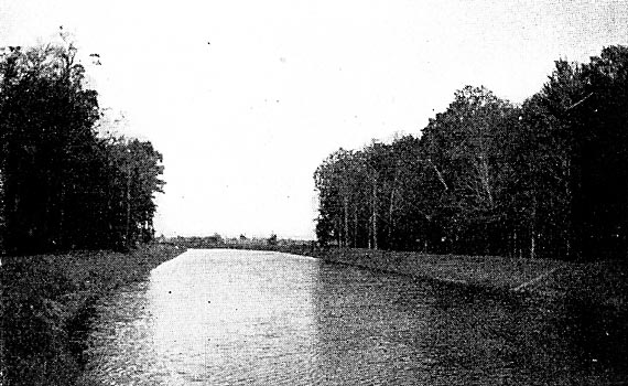
| |||
| Fig. 9. View Along the Canal. |
At the ends of the crossarms, on each side of the pole, there is a vertical brace of 1 1/4-in. by 1/4-in. iron 28 in. long secured to them by 1/2-in. carriage bolts. Before they are put in position all of the braces are dipped in tar. On the top of each pole a 3/8 by 5-in. lag screw enters the wood in a nearly vertical direction, and beneath the head of this screw a No. 6 B. & S. gauge galvanized iron wire is secured. This wire runs down the pole a few feet and is then connected to a No. 12 copper wire that runs to the bottom of the pole and is there formed into a grounding coil of five turns.
 |
| Fig. 10. Details of Pole Top. |
From the electric generating station at Hannawa Falls to the sub-station in the village of Potsdam, a distance of 4.5 miles, there are two circuits of aluminum cables, each cable consisting of seven No. so B. & S. gauge wires. These circuits are designed to deliver 375 kilowatts at 4,00o volts in the Potsdam sub-station, when the voltage at the generating plant is 4,400, which is supplied direct by the alternators there. Electric lamp and motor supply in Potsdam is carried out with the energy thus transmitted from Hannawa Falls at 4,400 volts, after the pressure has been lowered by stationary transformers at the former place.
On reaching Ogdensburg the 20,000-volt transmission line remains on poles until it reaches the generating station of the Ogdensburg Power and Light Co. and the Ogdensburg Street Railway Co. This station is located at the corner of Lake and River streets near the Oswegatchie River, at about one-quarter of a mile from the center of the business district. This station is a one-story stone building, 77 by 75 ft. on the ground. In this station there are three rooms, one for the steam engine and electric generators, one for the boilers, and one for the 20,000-volt transformers.
Concrete has been used to give the transformer room a fireproof floor. On entering this transformer room the two 20,000-volt circuits are connected with lightning arresters, and then pass to the oil switches and transformers. These latter are in two groups, one consisting of three 100-kw units, and the other group of two 150-kw transformers, all of the Westinghouse make. In the three 100-kw transformers the electromotive force is lowered to about 360 volts for delivery to a 300-kw rotary converter that supplies the railway feeders. By the two 150-kw units the three-phase current of the transmission line is transformed to 2,000-volt, two-phase current, for distribution to lamps and stationary motors.
In the engine room there is one horizontal tandem-compound steam engine, a long main shaft direct coupled to a 200-kw, 550-volt, direct-current generator, and belted to a 2,000-volt, two-phase, 60-cycle alternator of the came capacity, two 75-kw dynamos and a 300-kw, 550-volt rotary converter. From the engine shaft to the main shaft there is a belt connection, and a like connection to the two 75-kw dynamos. Connected to the long main shaft are four 100-hp turbine wheels. A canal from the Oswegatchie River supplies water at a head of is ft. for these turbines.
By means of the connections and belting just named, the four water wheels may drive the 200-kw generator for the railway load, and the 200-kw, two-phase alternator for general lighting and power purposes. With the belt from the engine shaft to the main shaft, both of the 200-kw generators just named, as well as the two 75-kw dynamos, may be operated with steam power. The 300-kw, 550-volt rotary is necessary only when energy from the transmission line is being used for the railway.
In addition to the foregoing apparatus, the engine room contains two tub transformers, each of which is designed to supply 6.6 amperes to 85 lamps, and the switchboard. Steam for the engine is produced by a pair of 250-hp boilers, in a room 57 by 59 ft. and separated from the engine room by a stone partition.
The general plan of operation is to carry as much as possible of the load with the four turbine wheels that use the water of the Oswegatchie River. Additional power is, as a rule, drawn from the transmission line, but at certain times, or when necessary, the 600-hp engine is operated. Steam coal brought by water costs $3.50 per ton in Ogdensburg, and it is delivered to the boiler room of the electric plant by carts.
The electric supply load of the station just described is used for 140 alternating-current, 6.6-amp. enclosed arc lamps, 8,000 16-cp incandescent lamps and 6o hp in induction motors. The 6o hp of motor capacity was the amount connected to the 2,000-volt, two-phase lines before the introduction of the transmitted energy from Hannawa Falls at Ogdensburg, and from plans then under way it is probable that the present stationary motor load there is much larger. Among the possible motor loads for the Ogdensburg system to take up is that of 25o hp at the elevator and conveyor of the Rutland railroad docks. To this figure may be added some 350 hp in flour mills, and another 200 hp in smaller industrial plants.
In addition to the above electric supply load, the station named operate the entire street railway system at Ogdensburg, which includes ten miles of single track and not less than fifteen motor cars and a sweeper, besides two cars without motors. The gauge of track is 4 ft. 8 1/2 in., the rails are of 48 and 52 pounds per yard, and the length of paved street covered is not more than 1,000 ft. The line has a maximum grade of 6 per cent., and it crosses three iron bridges with an aggregate length of 174 ft. Motor cars vary from 18 to 22 ft. in length, and each is of the single-truck type with 6.5 ft. wheel base. The motors are 12-A Westinghouse. Closed cars have electric heaters. No connection exists between the street railway tracks and those of any steam road, and the street railway carries mail but no express or freight.
During the year ending June 30, 1904, the gross earnings of this road were $27,862.55. In the same year the expense of fuel for power was $287.25, which seems to indicate that most of the work was done with the local water power.
All of the new electric work at Ogdensburg has been done under the supervision of Mr. Edward F. Hawkins, manager and electrical engineer of the Ogdensburg Light & Power Co., and of the Ogdensburg Street Railway Co.
Plans for all of the hydraulic and electric developments about Hannawa Falls, and for the transmission lines to Ogdensburg and other points were from the office of Mr. Wallace C. Johnson, of Niagara Falls, consulting engineer for the Hannawa Falls Water Power Co., and the work was carried on under his general supervision. Mr. Wm. B. Cogswell, of Syracuse, a director of the Water Power Co., has given the electric development of Hannawa Falls a large share of attention. To Mr. O. H. Tappan, secretary and treasurer of the Water Power Co., more perhaps than to any other man, is due the present success of the Hannawa Falls plant. Mr. Tappan has watched over both the financial and technical details of the enterprise, and his aim has been to sell wood pulp and electric energy, rather than stocks and bonds.
The office of the Hannawa Falls Water Power Co. is at Potsdam, N. Y.
