[Trade Journal]
Publication: Street Railway Journal
New York, NY, United States
vol. 10, no. 5, p. 280-282, col. 1-2
Three Phase Electric Transmission of Power Applied to Electric Railway and Mill Operation.
The first important application of electrical power transmission to street railway and other power purposes has just been installed by the General Electric Company at Taftville, Conn., the power being transmitted from Baltic to Taftville, a distance of nearly four and one half miles. It is a typical transmission by three-phase currents, in which motors of the synchronous type are used not only to operate one of the most interesting cotton mills in this country, but also the power station of the Norwich (Conn.) Street Railway.
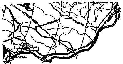 |
| Fig. I Route of Three-Phase Electric Line. |
E. P. Taft, who is largely interested in the Taftville cotton industry, long ago recognized the value of the available water power at Baltic, on the Shetugket River, near to which stood a ruined mill destroyed by fire some years ago, and having secured the property with the water rights, determined to utilize the power as soon as a successful means could be discovered. When the General Electric Company announced a practical solution of the power transmission problem, Mr. Taft carefully investigated the system and finally decided to adopt it for the operation of his cotton mills. The installation has now been completed, and the successful operation of the plant proves the advantages of the choice.
The Ponemah Mills are situated at Taftville, also on the Shetugket, and about three miles distant from Norwich. The original mill was operated for nearly a score of years by water power taken directly from the river, and when the new mill was erected it was found necessary to drive it from two 350 H. P. Corliss engines, the existing dam being insufficient in capacity. In Fig. 1 are shown the relative positions of the generating station at Baltic and the receiving station at Taftville. The line is nearly four and one half miles in length and is carried along the highway up the river, skirting its bank in places and crossing it at intervals to shorten its route.
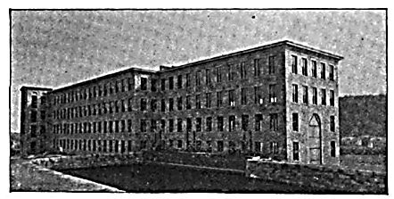 |
| Fig. 2Baltic Mill, Showing Reservoir and Intake Gates. |
The rebuilt mill and generating station at Baltic is shown in Fig. 2. In the basement of this building are the wheel and dynamo rooms of the generating plant. The mill is of four stories, built of stone, and will presently be used as the Ponemah Mills in the cotton weaving industry. 400 ft. above the mill a fine stone dam 525 ft. long has been thrown across the river. The effective head on the turbines is thirty-two feet, and the water available, even in the driest seasons, is sufficient to furnish not less than 1,500 H. P.
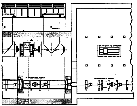 |
| Fig. 3.Part Plan of Turbine and Generator Rooms. |
Fig. 3 is a plan of the basement of the mill in which the power plant is located. It will be seen that the turbines are belted to pulleys on the main line shaft extending the whole length of the wheel room, and continuing through the partition walls into and along one side of the generator room. The pulleys are thrown into or out of action by Hunter clutches mounted with pulleys on quills, so that any or all of the wheels can be applied to driving the shafts. Similar pulleys and clutches are furnished in the dynamo rooms for throwing in or out the various machines that may there be placed.
| |||
| Fig. 4.Turbine Room at Baltic. |
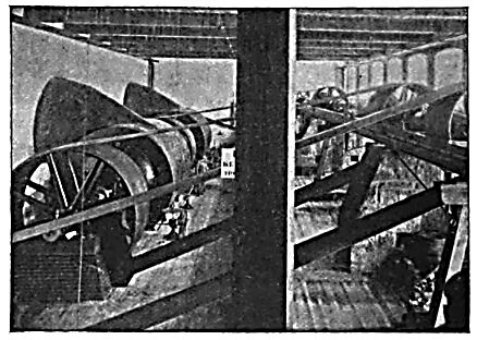
Fig. 4 shows the wheel room and the arrangement of the turbines and line shaft. There are three double, forty-two inch, horizontal wheels and one double, twenty?seven inch wheel, the former developing 800 effective H. P. each, at 157 revolutions per minute, and the latter 300 H. P. at 244 revolutions per minute. The belts pass obliquely upward to the pulleys on the line shaft, and the turbines are kept at speed by Schenck electric governors, which have proved themselves capable of doing very fair service. The wheel plant and shafting were made and installed by the P. C. Home Company, of Gardiner, Me. The line shafting is supported by heavy iron girders set on stone piers and additionally braced by timbers.
| |||
| Fig. 5.Portion of LineTaftville Transmission Plant. |
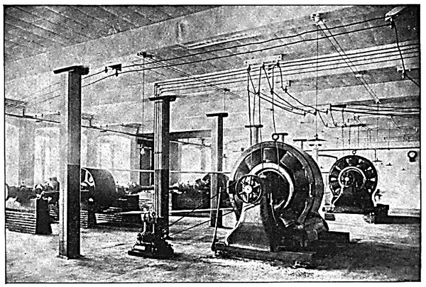
The dynamo room (Fig. 7), besides the shafting, is occupied by two 250 General Electric three-phase generators, delivering current to the line at 2,500 volts. Each machine is provided with its own exciter, a three kilowatt, bipolar dynamo. The three-phase machines run at 600 revolutions per minute, and are set so firmly on substantial foundations as to run with scarcely a perceptible vibration. The driving pulleys on the main shaft are fitted with Hunter clutches, so that either machine can be dropped out without the slightest disturbance to the service.
| |||
| Fig. 6.Switchboard in Baltic Mills. |
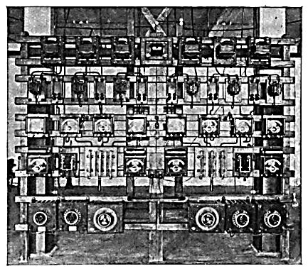
The generators are connected to a common switchboard (Fig. 6), and may be run in parallel whenever desirable. To this end the board is furnished with synchronizing apparatus, the acoustic synchronizer being mounted on the face of the switchboard, and the equalizing switch being at the back. The most interesting novelties on this switchboard are the high voltage switches on the lower part of the board. These are mounted on marble bases, with substantial barriers erected between the switchblades, so that the circuit at full load and voltage may be broken without the slightest danger of arcing across from point to point. They have been amply tested, and have proved their ability to cope with the trying work required of them with the greatest ease.
| |||
| Fig. 7.Generator Room, Baltic MillsTaftville Transmission Plant. |
The generators fall into parallel easily, and run as smoothly together as would a couple of railway generators. No artificial load is used in throwing them together, none having proved necessary.
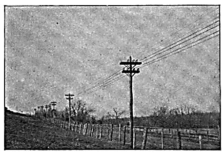
The line, a characteristic bit of which is shown in Fig. 7, is a good piece of construction on substantial wooden poles placed 100 ft. apart. The upper wires on the cross arms are of No. O bare copper, and form the original three-phase circuit designed for the transmission. The wires on the lower cross arm are No. 0000 insulated wire, and are four in number. They were originally intended for a railway circuit, the generators for which were to be installed at Baltic to feed the Norwich Street Railway; but as the amount of copper necessary to do the work successfully appeared too great, the system was changed, a second three-phase generator and motor were added, and three of the four proposed feeder wires were utilized for the three-phase circuit. All are supported on the General Electric Company's standard oil insulator, the fourth No. 0000 wire forming a convenient relay in case of accident to any of the others.
| |||
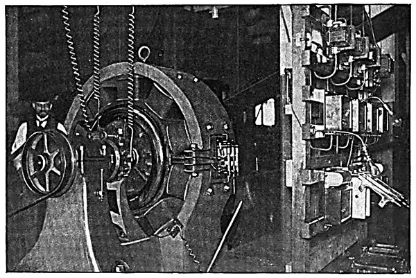
| Fig. 8.Synchronous Motors Operating Railway GeneratorsPonemah Mills. |
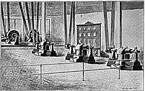
At Taftville the three-phase circuits are led into the basement of the new mill, where they drive two three-phase, synchronous, self starting motors (Fig. 3), identical in size with the generators at Baltic. A view of this basement is given in Fig. 8, and one motor and a switchboard are shown in Fig. 9. Both motors are belted to a jackshaft which drives the mill machinery, and from which the railway generators are operated directly. The pulleys on this shaft are being equipped with friction clutches, so that the load can be thrown in and out of circuit.
The efficiency of the complete transmission at full load, from the power applied to the dynamo pulley to that delivered to the motor pulley, is just 80 per cent.
| |||
| Fig. 9.Synchronous Motor and SwitchboardPonemah Mills. |
The motors start entirely unaided, coming up to synchronous speed in about fifty seconds from the time the current is thrown on. They are, like the generators, separately excited, the exciters being driven from the pulleys on the end of the motor shaft.
This is believed to be the first application of the three-phase system to street railway operation, and the success of the installation will go far toward popularizing the method for cases where it is applicable. In this connection a brief description of the Norwich Street Railway may not be without interest.
The Norwich Street Railway Company was organized in 1875 to take over the property of the Norwich Horse Railway Company, which was sold under foreclosure. The property of the company was operated by horse power until the spring of 1892, when the road, having been sold to Messrs. Shaw, Pond and Mason, of Boston, and Charles P. Cogswell, of Norwich, equipment with electric motors was commenced. The tracks were relaid with new fifty pound steel rails, on a well ballasted roadbed, and cars of modern type were obtained from the Newburyport Car Company. The motor equipment purchased was of the W. P. type.
In January, 1893, a syndicate of Boston capitalists, headed by Messrs. Tucker, Anthony & Company, bought both the Norwich and New London systems entire, with the exception of the interests retained by Messrs. Shaw and Cogswell. The electric equipment has been rapidly extended during the past year, and the road is now excellently equipped and operated under the efficient management of E. P. Shaw, Jr.
