[Trade Journal]
Publication: Electrical Age
New York, NY, United States
vol. 38, no. 2, p. 63-69, col. 1-3
The Animals Power and Water Company
The Largest Hydro-Electric Development in Colorado
By F. O. Blackwell
THE future growth of the mining industry of Colorado is largely dependent upon the development of the large bodies of low grade ore which have been passed over in the search for bonanza deposits. Mines with rich enough ore are of course able to stand a high cost of labor and power, but the lower grade properties must be worked on a large scale with laborsaving machinery and cheap power to be profitable.
The cost of steam power, even in the mining camps reached by railroad, is seldom less than $100 per horse-power year, and, when coal has to be hauled considerable distances over mountain roads, it is generally over $200. The utilization of the energy of the mountain streams, where high falls can often be found, has been of the greatest value in lowering the cost of mining and made possible the operation of many properties that would be unable to succeed under steam power.
| |||
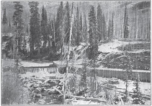
| Fig. 1. the Diverting Dam and Head Gate at Cascade Creek, A Tributary of the Animas River in Colorado. the Present 6000-H. P. Development of the Animas Power & Water Company Utilizes Only the Waters of This Creek. |
As there are no large rivers in Colorado, it is to high head rather than to volume of flow that we must look for any large amount of power. There is another difficulty in the wide variation of flow between the wet and dry seasons and the freezing up of the streams in the mountains during extreme cold weather. In order to get reliable power, either a steam reserve must be provided or a sufficient storage reservoir secured to equalize the flow.
The recently completed power plant of the Animas Power & Water Company, the largest water power in Colorado, supplies electrical energy to the San Juan mining district in the Southwestern part of the State. The ore, in general, is of a medium grade, requiring much power for milling and concentration. Hence, electric power at a comparatively low cost is of the utmost importance.
 |
| Fig. 2. A Plan of the Existing and Proposed Development of the Animas Power & Water Company in Colorado. |
The properties of the company are located in San Juan and La Platta Counties, between the towns of Silverton and Durango, on the Animas River. The stream between these two points flows through a deep and narrow canyon, with a total fall of approximately 1800 feet. The ultimate water-power development contemplated by the Animas Company, as shown in Fig. 2, includes the construction of diverting dams on the Animas River, Cascade and Lime Creeks, together with the necessary waterways for conveying the flow of the streams to a large reservoir, from which a flume leads to a small forebay, located 1000 feet above the Animas River, flowing in the canyon below. From the forebay, the water falls through riveted steel pipe to the water wheels in the power house.
When all the power generated in power house No. 1 is sold, it will be possible to make another development by means of a high dam about 3 miles below the present generating station. From this dam, with 2 1/2 miles of waterways, a head of 500 feet can be developed.
 |
| Fig. 3. A Sectional View of the Power House, Showing Transformers, Switches, and Generating Units. the Electrical Equipment Was Supplied by the General Electric Company, of Schenectady, and the Hydraulic Equipment by the Pelton Water Wheel Company, of San Francisco. |
The present water-power development of the company, which has a rated capacity of 6000-H. P., utilizes only the waters of Cascade Creek. This stream above the diverting dam has a drainage area of 30 square miles, the average elevation of which is approximately 12,000 feet above sea level. The total area tributary to the large storage reservoir, however, is about 48 square miles, the additional 18 square miles being the catchment area tributary to the reservoir itself.
Before proceeding with the construction of the Animas plant, a measuring weir was constructed on Cascade Creek, near the site of the present diverting dam, and the depth of water flowing over the weir was carefully gauged by taking hourly readings throughout the day for a period of one year. From these discharge measurements, together with a study of the rainfall records and other stream measurements made in Southwestern Colorado on rivers having similar characteristics to Cascade Creek, it was estimated that the annual run-off of the drainage area above the reservoir would never be less than 70 per cent, of the minimum precipitation of 14 inches, and that there would always be sufficient water to operate the plant.
The discharge of Cascade Creek is very fluctuating, varying sometimes as much as 100 per cent, during a single day, due to the freezing up of the stream during the winter nights, followed by the subsequent thawing during the day. The storage reservoir is sufficient to equalize the yearly run-off from the catchment area tributary to it, and the power plant is therefore independent of any fluctuations in the flow of the stream.
DAMS AND FLUMES
A small dam has been constructed on Cascade Creek to divert practically all the water of the stream to a box flume 3 1/2 miles long, with an inside depth of 6 feet, and a width of 8 feet. This flume leads to a natural waterway, known as Little Cascade Creek, the water flowing along the bed of the creek for a distance of 2 1/2 miles to a point where a second small dam has been constructed for again diverting the water into another flume of the same dimensions. The latter is half a mile long and empties into Cascade reservoir, from which point a third flume 8800 feet in length and 3 1/2 inches by 4 feet 8 inches in the clear, leads to the forebay.
The flume from Cascade Creek to the reservoir must be of sufficient size to carry the flood waters of the stream, while that to the forebay is designed for the equalized flow.
The largest of the waterways, Cascade Flume, was constructed to a slope of .002 or 2 feet to a thousand feet. The discharge was calculated by Kutter's formula for the flow of water in open channels, which for measures in feet is as follows:
 |
For the flume in question the coefficient of friction was taken at .012. This figure is conservative and was determined by a careful study of the conditions under which the flume would operate, and from tests made on the number of flumes in actual service. The velocity as determined from the above formula with the water running to within I foot of the top of the flume, or at an actual depth of 5 feet, is approximately to feet per second. As stated, the flume is 8 feet wide in the clear so that with 5 feet of water, the capacity would be 400 cubic feet per second.
As the flume was constructed in an almost inaccessible country, where the ground is covered with snow for six months out of the year, all the work had to be carried on in the summer and fall. Sawmills were erected on the ground and the lumber was delivered at accessible points along the line of the flume, from which points construction was started. By working mules inside the completed portions of the flume the lumber was hauled to the workmen at both ends and in this manner the work was carried to completion.
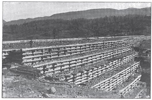
The flume consists essentially of three longitudinal stringers, with supports every 6 feet, one stringer being in the center and one at each side. The middle stringer is 6 by 8 inches, and the side timbers are 4 by 8. A yoke of 6 by 6-inch timbers, with a knee brace on each side to hold the yoke in position, was framed at every 6 feet along the length of the flume, and between these braces a smaller yoke of 4 by 6-inch timbers was framed, the latter having no knee braces. The box of the flume is made np of a double thickness of inch boards laid with joints broken. All flumes are covered in order to prevent loss of water by evaporation in summer and the probability of freezing in winter.
| |||
| Fig. 4. the Dam at Cascade Reservoir. |
The crib dam, which forms the reservoir, is 750 feet long at the crest, which is 50 feet above the ground. The dam has a width of 90 feet at the base and 40 feet at the top, the foundations being carried 33 feet below the natural surface of the ground to bedrock. It is constructed of round logs, 10 feet between centers, each log being fastened to the next one underneath by means of 3/4-inch pins, the cribs being filled with rock. The upstream side of the dam is vertical and to assist in making it watertight, three layers of heavy planks are nailed to the facing logs. The first layer of planks is 2 inches thick, and on top of this is nailed a layer of tarred felt, which is followed by a double thickness of 2-inch boards with the joints broken. This dam is temporary, and will ultimately be replaced by a higher one of masonry, which will make a much larger reservoir.
A natural rock spillway for discharging the overflow of the reservoir to a waterway leading to the Animas River was constructed to one side of the dam.
The reservoir is 3 miles in length and 1 mile in width at its widest point, the total storage capacity being more than 1000 million cubic feet. The water may be drawn from the reservoir to a depth of 50 feet by means of two 36-inch pipes encased in concrete, the discharge to the pipes being controlled by sluice gates at the inside face of the dam.
The forebay, which covers an area of approximately five acres, was formed by constructing an earth dam with a 3-foot core wall, carried to bedrock in order to prevent leakage. The dam is 30 feet high and 100 feet long at the crest.
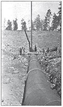
PIPE LINE
The pipe line to the power house is 2800 feet long and was furnished by the Pelton Water Wheel Company, of San Francisco. It starts with a conical section of riveted steel pipe, tapering from a diameter of 60 inches to 44 inches and embedded 25 feet below the crest of the forebay dam. The formation of a vacuum in the pipe line is prevented by the erection of a lo-inch standpipe on top of the steel pipe immediately to one side of the gate valve at the forebay. This will always insure the pipe line being filled with either water or air. The diameter of the pipe varies from 44 inches to sections of 40 inches, 36 inches and 34 inches, the largest being used at the forebay and the smallest at the power house.
The lower end of the pipe is subjected to a hydrostatic pressure of approximately 430 pounds per square inch, and is made up of 11/16-inch steel plate, double butt strapped and triple riveted in longitudinal scams, and single butt strapped and single riveted in circumferential seams. This section of pipe has also riveted to it a rolled steel flange to which is bolted a Y branch, tapering to two 20-inch outlets for connecting with the gate valves controlling the discharge of water to the two impulse wheels. The minimum thickness of pipe is at the forebay end where 1/4-inch plate was used.
| |||
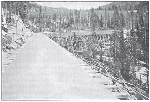
| Fig. 5. the Power House and Part of the Pipe Line. |

The pipe was made in 30-foot sections fitted with welded steel angle flanges, the sections being bolted together with composite lead and copper gaskets between these flanges. The heaviest sections weighed 6 tons each, the total shipping weight of the pipe line being nearly 700,000 pounds. All sections were tested before shipment to pressures 50 per cent, in excess of the hydrostatic pressures for which they were designed. A temporary track, mine hoist and cable were used in hauling the pipe up the bluff, the grade in some places being as steep as 85 per cent. The downward thrust of the pipe is taken up by a large concrete block at the power house, although numerous concrete piers along the line of the pipe assist in supporting and keeping it in place.
| |||
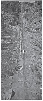
| Fig. 6. A Part of the Pipe Line, Showing the Temporary Track for Hauling the Pipe Up the Bluff From the Power House. |
POWER HOUSE
The generating station is on the bank of the Animas River 2 1/2 miles above the town of Rockwood and almost immediately under the forebay. The building is of substantial fireproof construction and built of concrete, brick and steel. The base is of concrete and forms the foundation for the hydraulic and electric machinery. Brick was used for the side and end walls. "Ferro-inclave" and cement are used for the roof covering, the switchboard gallery also being of "ferro-inclave" and floored with cement.
A center row of steel columns supports the roof, and also carries one line of riveted girders for a 15-ton hand-power traveling crane. The inside length of the power house is approximately 108 feet, the width 64 1/2feet, and the height from the main floor to the underside of the roof trusses is 30 feet.
HYDRAULIC APPARATUS
The pipe line enters the rear wall of the building, passes through the basement and terminates in a Y branch and two 20-inch gate valves, which control the admission of water to the needle nozzles of two 3000-H. P. water wheels. These wheels are of the impulse type, built by the Pelton Water Wheel Company, and are capable of carrying an overload up to a maximum of 4000 H. P.
The effective head is 970 feet, and the wheels run at a speed of 300 revolutions per minute. They are 8 feet in diameter and are overhung on an extension of the alternator shaft, which at the bearings is 14 inches and at the revolving field 16 inches in diameter. The bearings are 42 inches long and have water-cooling coils in the lower half for keeping down the temperature of the oil. If necessary, water may also be passed through a 5-inch hole along the center of the shafts to assist in keeping the bearings cool.
Lombard oil-pressure governors are belted to the water-wheel shaft. Each is furnished with a separate oil pump of sufficient capacity for operating the two governors, and so connected that one may furnish oil for either or both governors, thus obviating the necessity of shutting down a wheel in case it is desired to make repairs on either pump.
As shown in Fig. 3. each wheel is equipped with two 6 1/2-inch needle-nozzles, one immediately above the other, the upper controlling the admission of water to the wheels and the lower being a by-pass nozzle. By means of a system of toggle-joint levers, which are operated by the governors and connected between them and the two needles of each water-wheel nozzle, the lower or bypass needle is opened whenever the upper needle is being closed, and vice verse, both nozzles being designed to secure by this means a constant discharge of water in the pipe line, irrespective of any change in load on the wheels, and thus avoid dangerous rams in the long penstock. Comparatively little water is wasted, due to varying loads throughout the day, as, by means of a hand wheel and right and left-handed screw, which is connected to the toggle-joint mechanism, the station attendant can adjust the motion of the needle nozzles, so that at the maximum load, which is likely to come on at any particular portion of the day, no water will flow through the by-pass nozzles.
ELECTRIC APPARATUS
Each water wheel drives a 2250-KW. General Electric alternator of chine being large enough to excite the revolving-field type, which generates three-phase current at 60 50-KW. capacity and are wound for 125 volts direct current, either machine being large enough to excite the fields of both alternators.
The power house has been designed for an ultimate capacity of four of these units with water wheels. The low-potential suitable for long-distance transmission by two banks of water-cooled oil transformers, each bank consisting of three 750-KW. units, wound for 4000 volts on the low-tension and 50,000 volts on the high-tension side. Each transformer tank, in order to completely immerse the core and windings, carries 600 gallons of oil, and is, therefore, placed in a closed fireproof compartment separated from the generator room by steel bulkheads. A heavy sheet-iron door fastened to the bulkhead provides access to the transformers. The six compartments occupy the space immediately under and along the front end of the switchboard gallery.
| |||
| Fig. 7. One of the 750-Kw., 4000-50,000-Volt Transformers, Built by the General Electric Company, of Schenectady, N. Y. |
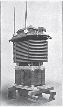
The cooling coils are extra heavy wrought iron lap-welded pipe, with electrically welded joints and capable of withstanding a pressure of 1000 pounds. A water flow of five gallons per minute is sufficient to absorb all the heat generated in the transformer.
The switchboard is mounted on the gallery and consists of two combined generator and step-up transformer panels, two exciter panels, two outgoing line panels and a regulator panel. The latter controls a Tirrill regulator, which is mounted on the panel and by automatically cutting in and out resistance in series with the exciter field circuits, it maintains constant voltage across the station bus-bars irrespective of the load or power factor. It may also be connected to over-compound or increase the potential with load. The switchboard is of black enameled slate, and no high-potential leads are brought to the panels.
| |||
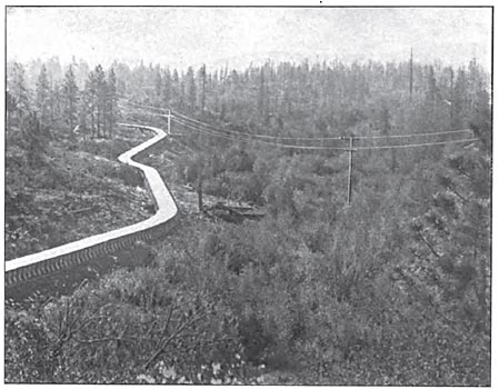
| Fig. 8. Part of the Flume Connecting Cascade Reservoir With the Forebay. A Part of the Transmission Line is Also Shown. |
The 4000-volt alternator switches and the 50,000-volt transformer and line switches are of the oil type and operated by 125-volt direct-current motors, controlled from small pilot switches on the panels. All of the oil switches are mounted on the switchboard gallery and miniature red and green lamps on the panels indicate automatically whether an oil switch is open or closed.
There are two outgoing three-phase 50,000-volt transmission lines, and each line with a bank of transformers and an alternator may be operated as one unit and independent of the rest, or the two outgoing lines may be operated in multiple by closing disconnecting switches in series with the high-tension bus-bars. By means of a 4000-volt transfer bus, which is mounted on the switchboard gallery, the alternators and transformers may also be connected for parallel operation.
The wiring consists of insulated cables in conduits and bare wire in brick and concrete compartments so that any damage resulting from an arc is limited and cannot injure the adjacent circuits.
| |||
| Fig. 9. A Part of Cascade Flume Extending From the Diverting Dam to the Storage Reservoir. |
| |||
| Fig. 10. A Part of the Forebay Dam, Showing the Standpipe. |
Along the rear wall of the building and separated from each other by concrete walls are mounted the lightning arresters and line disconnecting switches. The high-tension bus-bar compartments are on the first floor of the building and underneath the 50,000-volt transformer and line switches, which are mounted on the gallery above. All the oil switches/ transformers and alternators are equipped with air-break disconnecting switches so that they can be cut off from the system for repair and inspection.
The electrical equipment was furnished and installed by the General Electric Company, of Schenectady. N. Y.
TRANSMISSION LINES
Two wooden pole lines have been constructed from the power house to Silverton, Col., a distance of 25 miles, each pole line carrying a 50,000-volt three-phase 60-cycle circuit.
The poles were obtained from the timber of the region and range in height from 28 to 35 feet and are 7 1/2 inches in diameter at the top.
Each transmission line is of sufficient capacity for carrying the entire output of the generating station so that in case of an accident to any one line it may be shut down for repairs without interfering with the delivery of power.
On leaving the power house the lines separate, one running up the Animas canyon and the other over the hill to the forebay and across country to Silverton.
The region traversed by the lines is frequented by numerous and destructive snow slides so that while either line is apt to be disabled from an accident of this sort it is not probable, in view of the lines running through different sections of country, that accidents of this character will be simultaneous on both circuits. Under ordinary conditions the poles are spaced 250 feet apart, but where gullies or other depressions in the ground are crossed the span was increased and wooden towers were substituted for the poles. Some of these towers are 60 feet high with a base of 20 feet, each leg of the tower being securely fastened to blocks of concrete or else anchored to bedrock. The longest spans employed were over 1000 feet.
Porcelain insulators for the transmission lines were furnished by the R. Thomas & Sons Company, of East Liverpool, Ohio. They are made in two parts and consist of a 14-inch head and a shell which were shipped separately and cemented together on the ground. Each part was tested before shipment by subjecting it while wet to a potential of 50.000 volts. The assembled insulator will withstand a wet test of 75,000 volts between the pin and conductor without arcing over. A cast-iron pin is cemented in the insulator, two of the pins being bolted to a 4 by 6-inch cross-arm, while the third is fastened to the top of the pole, the three forming a triangle with 6-foot sides.
The conductor is an aluminum cable made up of six No. 8 B. & S. specially hard-drawn wires twisted four turns per foot around a hemp core and equivalent in conductivity to a No. 2 R. & S. copper wire, and was furnished by the Pittsburg Reduction Company.
The cable was supplied in lengths of 5000 feet and joints were made by inserting both ends of the conductor in a flat aluminum tube and twisting the latter a few times so as to grip the cables, the joints so formed being as strong as the conductor itself, which has an ultimate strength of 24,000 pounds and an elastic limit of 14,000 pounds per square inch.
In putting up the aluminum wire, the sag allowed for the various spans at the different temperatures of stringing was taken in accordance with the following table:
 |
The table of sag and span was calculated so that under the worst conditions of strain, or at minimum temperature and a wind pressure of 20 pounds per square foot, the wire would not be stressed to more than its elastic limit. The method of calculation is fully described in the writer's paper printed in Section D, Vol. II. of the "International Electrical Congress" held at the St. Louis Exposition in 1904.
The sub-station at Silverton contains at present three 750-KW, step-down transformers and a switchboard for controlling the incoming lines and the distribution circuits. The transformers are similar to those installed in the power house with the exception that the low-tension windings arc wound for 17,000 volts, which is the potential of the distribution circuits. The power is delivered to the mining regions within a radius of from 10 to 15 miles of the sub-station and at each mine step-down transformers are again installed for reducing the potential to a suitable voltage for lighting and power service.
