[Trade Journal]
Publication: Street Railway Journal
New York, NY, United States
vol. 25, no. 13, p. 605-607, col. 1-2
LINE CONSTRUCTION FOR HIGH-PRESSURE ELECTRIC RAILROADS
An interesting paper on this subject by George A. Damon was read at the meeting of the American Institute of Electrical Engineers held in New York, March 24, 1905, by Prof. Sever, in the absence of the author.
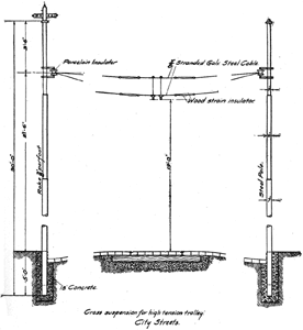
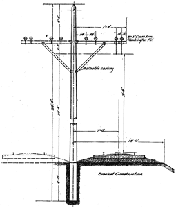
Mr. Damon first described the line construction in use on the Valtellina three-phase, Spindlersfeld single-phase and Huber experimental lines in Europe, and then that on the Lansing, St. Johns & St. Louis Electric Railway, the Indianapolis & Cincinnati Traction Company and the Bloomington, Pontiac & Joliet Electric Railroad in this country. As particulars and views of all of these lines except the last have been published in these columns, and as a description of the Pontiac overhead construction appeared last week, the diagrams of the Pontiac line construction are published herewith, together with Mr. Damon's general conclusions:
 |
| Suspension for High-Tension Trolley in City Streets—Bloomington, Pontiac & Joliet Railway |
REQUIREMENTS OF INSTALLATION
Bearing in mind the distinct requirements of the three classes of roads already referred to, the problem of line construction may be discussed under the following heads:
1. Pressure and Insulation.
2. Location of Conductor.
3. Requirements for Safety and Stability.
As an entire paper might be devoted to any one of these subjects, there is offered an opportunity for considerable discussion.
Pressure and Insulation.—The single-phase lines now in operation in this country have 3300-volt trolleys, and several lines under construction have also decided to use this pressure. From present appearances, therefore, 3300 volts is to be the standard for interurban lines. It would be well, however, to consider just at this time whether it would not be advisable to use a trolley pressure of 6000 volts. From an operating standpoint there seems to be no reason why this higher pressure is not just as practicable as a lower one; and to get the full benefit of all the advantages inherent with the high-tension system the higher pressure should be adopted.
Even if a few of the first roads are built with a 3300-volt trolley, there is no reason why, with the catenary suspension, the insulation provided should not be capable of standing a working test of 6000 volts, so that when the time comes to double the pressure the expense of the change will be a minimum.
For steam railroad conditions, the larger amount of energy required indicates that a pressure of at least 15,000 volts will probably be desirable. Just where to strike a balance between the cost of copper and the cost of insulation for steam road work is a problem which should be carefully worked out; but there seems to be no reason at this time why pressures of over 10,000 volts should not be considered.
The catenary form of suspension affords so convenient a method of insulation that it should become standard practice for interurban electric lines. When selecting an insulator for this construction, mechanical strength should be the first consideration, and a few cents more spent on the insulator will insure an abundance of insulating qualities. As far as insulation is concerned, there is no reason why the catenary construction could not be operated at more than 30,000 volts, if desired. For pull-offs and cross suspensions to iron poles special porcelain insulators are being designed and used with success.
It has long been admitted that dry wood is one of the best insulators. The convenience with which a wooden rod fitted with suitable terminals can be worked into an overhead construction will commend this form of insulation. Impregnated with an insulating compound, and of sufficient length to withstand high-pressure tests, the long wooden insulator is applicable to the insulation of guy wires, anchors and cross suspension wires. Its use in actual practice will be watched with interest.
The use of a wooden bracket to hold the insulator for supporting the catenary will probably appeal to some as a step backward. As far as looks are concerned, however, it may be said that a wooden bracket of a section 3.5 ins. x 5 ins. presents an appearance fully as attractive as the ordinary cedar pole to which it is attached; and that a double-track road with a line of center poles equipped with wooden brackets will be much less offensive from an esthetic point of view than a double row of side suspension poles raked outward in the usual fashion.
The wooden bracket has an element of safety not possessed by an iron support, as the insulating properties of the wooden arm would be useful in the case of the failure of an insulator. Unless the wooden bracket were wet it would safely hold up a 6000-volt catenary until the line could be repaired.
LOCATION OF CONDUCTOR AND COLLECTOR SYSTEMS
For moderate speed roads the natural tendency will be to have the trolley wire where it has proved to be so thoroughly satisfactory—that is, over the center of the track, and to continue to use the present trolley harp and wheel. For speeds not exceeding 40 m.p.h. to 50 m.p.h. at trolley pressures up to 3300 volts, this arrangement will work satisfactorily.
For high-speed electric lines there will be little objection to the conductor wire remaining over the track, provided it is properly suspended; but the danger of the ordinary trolley wheel jumping off the wire at high speeds will, no doubt, suggest the use of some form of collector other than the wheel. The bow, the roller and the shoe will each find advocates until more experience has been obtained and the results are reported and discussed.
Special cases will arise such as the installation of a high-pressure conductor wire over a road already equipped with a direct-current trolley, as was the case with the Ballston, N. Y. road. In such an event the catenary construction can be very nicely adapted to suspending the wire at the side of the track. This location could be advocated for an entirely new installation on the grounds of cheaper first cost and some additional safety in case the wire should break and fall, but both these arguments lack sufficient weight to establish the wire in the side position as standard practice.
 |
| Catenary Suspension for Trolley on Private Right of Way on Bloomington, Pontiac & Joliet Railway |
For steam road conditions considerable objection may be found to locating the conductor wire over the center of the track: the danger to trainmen standing on top of the cars; the fouling of the conductor; the deterioration of the insulation, and the destruction of the wire and supporting cables by the gases of locomotives which may jointly occupy the tracks; the blocking of traffic when it is necessary to repair a broken wire—all these are serious drawbacks to this location of the conductor for heavy railroad practice. To avoid the deleterious effect of the locomotive gases it would seem to be imperative to place the contact wire at one side and as low as possible consistent with general safety. The advisability of installing an independent and duplicate system of conductors is also to be considered for lines of importance; this can be done only by putting the wires on opposite sides of the track.
 |
| Bracket Construction on Bloomington, Pontiac & Joliet Electric Railway |
The Huber system appears to have been carefully worked out, and at the present time is the best suggestion for a solution of the line problems in connection with the electrification of steam roads. There is one serious objection to the arrangement, but this can be overcome. The contact wire carried from pole top to pole top is liable to break, and some form of support should be devised to prevent the broken ends falling to the ground. A double-catenary suspension system with one wire carried on an insulator at each end of a cross arm attached to the pole, say a foot from the top, could be provided, and the contact wire could be supported from the apex of triangular supports attached to the two catenary wires. This method would offer advantages over any system of guard wires or cradles which might be devised to catch the broken wire, as it would require three wires to be broken before any part of the system could fall to the ground.
REQUIREMENTS FOR SAFETY
Frequent Supports.—Whatever method of construction is followed, every precaution should be adopted to prevent accidents to the public or employees from the loose ends of a broken live wire. Suspensions or supports properly installed every 10 ft. to 15 ft. will lessen this danger.
 |
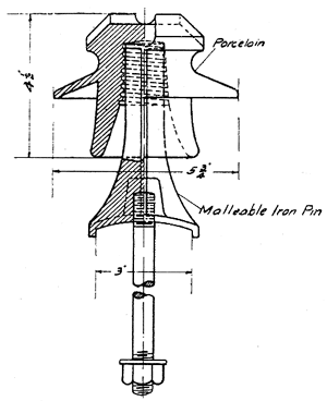
| Malleable Iron Pin Used on Bloomington, Pontiac & Joliet Line |
With bracket construction having poles about 100 ft. apart, there will be no need of a double-catenary suspension for the wire which is to be used with an under-running collector. In such a case, the double suspension would mean twice as many insulators as would be required with the single catenary, thus decreasing the insulation resistance and increasing the chances for trouble. With what is known as the "tower" method of construction—using long spans—the double catenary, spreading at the points of insulated supports and converging together at the center of the span, will be found desirable. The necessity of keeping the wire from swaying will justify the double catenary in this case, and the fact that the number of points of support is reduced by using long spans will more than balance the use of two insulators at each support.
The frequent clips holding the contact wire are not only advantageous from the standpoint of additional safety, but they contribute to the permanency of the construction by keeping the wire almost perfectly horizontal at all temperatures, and thus avoiding the bending of the wire up and down at the support points every time the collector passes. The only disadvantage to clips holding the wire every few feet is the tendency for the trolley wheel to spark at these points. This is not a serious objection if a collector similar to the bow device is used, in which case there will be no interference between the collector surface and the mechanical clips.
Protection From Sleet.—In a hard sleet storm every attachment connected to the wire will naturally be the cause of additional trouble. The arcs due to a coating of ice between the wire and the collector will be much more vicious at 6000 volts to 15,000 volts than at 500 volts, but there is no occasion to become alarmed at the possible danger from this source. In this country one of the high-pressure lines using a trolley wheel on a 3300-volt wire has already passed through a hard siege of sleet; and though the sparking was spectacular, very little damage was done. The frequent trolley supports, however, added considerably to the sparking.
Greased trolley wires are sometimes used to prevent the trouble caused by sleet; it would be interesting to learn the experience of members of the Institute with this device. It is well known that the grease finish of an aluminum wire prevents the collection of sleet upon the wire, and it may be possible that a coating of grease on the high-pressure conductor wire would entirely obviate this trouble. It is evident that with a collector taking the current by means of a contact made on the top of the wire, as in the Huber system, the trouble from sleet would be a minimum. In those kinds of sleet storms in which icicles are formed and hang from the wire, a top-bearing collector would have every advantage, but when the sleet freezes equally all round the wire, the lighter pressure of the top-bearing contact might put the Huber collector at a disadvantage.
Transmission Lines.—The transmission lines from the power plant to the sub-stations will be at a higher pressure than the trolley pressure, and will therefore require careful treatment. For a road which is to be built economically, a single set of transmission wires serving all of the static transformer stations in parallel will be sufficient. These transmission wires will ordinarily be carried on the tops of the same poles which support the trolley bracket.
The next refinement would be to have a separate set of transmission lines from the power house to each sub-station, making it possible to put the overload protective devices on the central station switchboard and thus eliminate the sub-station attendance. With this multiplicity of wires and consequent higher first cost adopted, it is but one step further to separate entirely the two systems and to install two pole lines on the same right of way; where the electric road is of the high-speed class this should be done.
 |
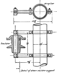
| Detail of Strain Insulator Support Used on Bloomington, Pontiac & Joliet Single-Phase Railway |
To be consistent, however, in insuring safety to the public, it would be well to advocate as standard practice the plan of carrying the high-pressure transmission lines entirely around small towns and cities instead of through them. If the transmission lines are too dangerous to be carried on the railroad company's trolley poles, then there is more danger in carrying them along the streets and over the network of telephone wires inside the corporate limits. The problem of the proper regulation for this situation is one that will shortly have to be faced.
The first investment in the transmission line, the cost of maintenance, and the loss by leakage—all these can be cut in half by thoroughly grounding one side of the single-phase transmission line so as to use the earth as one leg of the circuit. An actual trial of this suggestion to further simplify the distribution system is under contemplation, and no doubt will furnish valuable information as to its effect on telephone and telegraph lines as well as data in connection with the resistance of the earth with alternating currents.
Grounded Guard Wires.—Where the transmission lines pass over other wires there should be a cradle of grounded wires to prevent a broken transmission line from coming in contact with a foreign wire. This cradle will be of little use unless it is of ample dimensions. Some effort has been made on European roads so to install grounded wires that the breaking of a conductor would at once cause the live end of the wire to make a contact with the grounded guard wire, but in two cases which have come to notice the grounded guard wire caused more trouble, than it eliminated; for this reason it was soon abandoned. In order to encourage the discussion of the unsettled features of line construction for high-pressure electric railroads the following are offered as
GENERAL CONCLUSIONS
1. There are no reasons why the standard pressures of the conductor wire for interurban electric lines should not be at least 6000 volts; this is suggested as a standard in order to provide for interchange of equipment.
2. For the electrification of steam roads a pressure of about 15,000 volts on the conductor wire is desirable.
3. For electric interurban lines the present tendency is toward the catenary form of suspension, with the trolley over the center of the track. A connection should be made about every 10 ft. between the steel catenary wire and the trolley wire.
4. For steam railroad conditions a contact wire at the side of the track appears to offer the greatest advantages. Some form of construction should be adopted, however, to prevent the falling of the conductor in case it should break.
5. A successful bow collector for interurban work and a contact arm for steam road installations similar to that in use by the Huber system would allow the location of the contact wire to be standardized.
6. A trolley wire 20 ft. above the center of the track is suggested for interurban roads. For steam road electrification the height of the contact wire at the side of the track could be made standard at 16 ft.
