[Trade Journal]
Publication: Electrical World and Engineer
New York, NY, United States
vol. 41, no. 1, p. 5-10, col. 1-2
The First Three-Phase Power Transmission Plant
in Europe Operating at 30,000 Volts.
BY DR. H. BEHN-ESCHENBURG.
THERE has been in uninterrupted operation for the past two years, at 30,000 volts, the power transmission line of the Machienenfabrik Oerlikon, between Hochfelden and Oerlikon, which is the first installation of its kind in Europe, and was operated at 15,000 volts between the years 1891 and 1900. Now that this trial period has come to an end, it may be of interest to collect the valuable and unique experiences gained by the operation of this transmission, the first one in Europe using so high a pressure.
The total mean energy, delivered by the primary stations at Hochfelden and Glattfelden, working in parallel, is 550 k.v.a., with a power factor of 0.85. The power station at Glattfelden is located about 2 km from the Hochfelden station and furnishes about 120 k.v.a. at 5,000 volts to Hochfelden, where the current is raised to 30,000 volts and is connected in parallel with the current generated at Hochfelden. The exciters of the Glattfelden generators are regulated at Hochfelden.
| |||
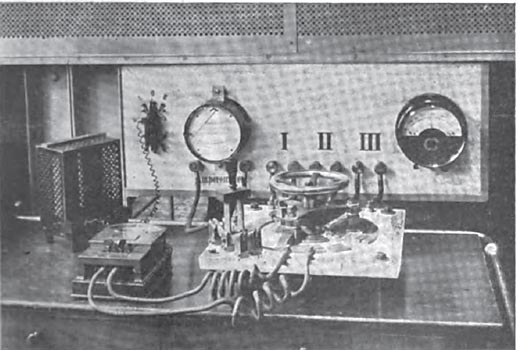
| Fig. 1. Interior View of Hochfelden Station. |
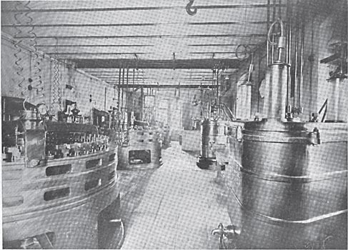
The Hochfelden station, Fig. 1, contains three turbines connected to three generators of the "Lauffen" type of the Oerlikon Company, constructed in the year 1891. Each machine has a capacity of 1,200 amperes at too volts, at a speed of 187 r.p.m. and 50 periods. Each machine is direct-connected to a three-phase transformer of the same type as those shown at the Frankfurt exhibition in 1892 for the Lauffen-Frankfurt transmission line which has been frequently described. The transformation ratio of each transformer is 1:154. During normal running of the plant two generators and two transformers are operated. The high-tension winding of the one transformer is connected in star fashion, while the high-tension coils of the other transformer are separated for each phase and connected in series with the coils of the first transformer.
These transformers are, as is well known, standing in cast iron casings filled with oil. The oil is Continually pumped into and out of the casings by means of a pump, being cooled during this operation by passing through coils surrounded by running cold water. The transformer which transforms the current delivered by the Glattfelden station, is an ordinary air-cooled transformer with a ratio of 1:6, transforming the voltage from 5,000 to 30,000. The neutral wire of the low-pressure winding is connected to the water pipes.
The line consists of four copper wires 4 mm in diameter, which are suspended about 50 cm apart on 260 poles from 8 to 10 m. above the ground. Only three wires are in actual service. The resistance of one wire is 31 ohms. About 1.5 m below these wires, on the same poles, the two telephone wires (going and return), connecting the primary and secondary stations, are suspended. These two wires are crossed about 20 times along the entire distance. During the operation of the line no difficulty is experienced in carrying on a telephone communication. In case there is any fault in the insulation of the high-tension line or the telephone wires, the bells of the telephone are automatically operated on account of the disturbance in the symmetry of the electrostatic distribution and in this way the telephone is of service in case there are such defects. At the beginning, end and in the middle of the line, there have been placed for the past three years three Siemens lightning arresters (of the horn type) having a striking distance of 55 mm. These horns are operated almost every time there is a thunderstorm in the vicinity of the line, without ever having caused any interruption in the service. In fact for several years there has never been a decided service interruption, regardless of the fact that the line is run along the banks of a river and is exposed to frequent lightning discharges. There are an average of about 50 such occurrences, which strike the line, in one year. Since the plant was started no part of the transformers has ever been damaged by lightning. This certainly proves the great efficacy of high-tension lines with transformers inserted between generator and line. The much higher pressure which can be obtained by this arrangement when compared with the direct generator production, can in many cases equalize the extra cost of the transformers on account of the saving in line copper. In general this will also cause a reduction in the cost of generators, for the generator pressure may be selected at will, especially when bar winding can be employed.
 |
| Fig. 2. Various Types of Insulators. |
The line is connected to the transformers in the primary station by fuse wire 1 m. in length and freely suspended in the air. Formerly lightning rod points with copper leads were attached to each pole. Frequently during a thunderstorm lightning would strike across from the insulator support to lightning rod lead and the pole would be burnt. Two years ago all the lightning rods were removed. The 800 line insulators are of different types. About 100 of them are of the large Delta bell type, with an external rim diameter of 25 cm; there are 300 white porcelain insulators, like those used on the Lauffen-Frankfurt line; also 200 brown insulators of the same dimensions and 200 smaller plate-shaped insulators. The various types are shown in Fig. 2, the three smallest ones being used for interior wiring in the stations.
 |
| Fig. 3. High-Tension Switch. |
The secondary station may be cut out of service at full load by means of a high-pressure switch without the production of a spark. The switch is shown in Fig. 3 and is of the well-known type introduced by the Oerlikon Company in 1897. The spark distances are spanned by tubes. To prove the utility of this switch it may be stated that at 3,500 hp the three-phase circuit at 3,800 volts pressure may be opened without the least disturbance.
| |||
| Fig. 4. Oil-Insulated Water-Cooled Transformers. |
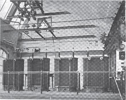
In the secondary station the line current is transformed from 30,000 to 230 volts. Up to about a year ago the transformation took place in four transformers of the 1891 type, similar to those in the primary station, two being connected in series on the high-tension side. The oil was circulated through water-cooled coils of pipe outside of the transformer by means of a pump. During the past year the old transformers have been replaced by 3 single-phase transformers of 150-k.v.a. capacity each, which have been connected in triangle fashion on the high and low-tension sides. These transformers, shown in Fig. 4, are also placed in oil, the latter being cooled, however, by being circulated through water-cooled coils within the transformers themselves. Without the water cooling the temperature rise at a 100-k.v.a. load is 35° C. Within a short time the transformers in the primary station will be replaced by a modern three-phase transformer of 450 k.v.a capacity with artificial air-cooling attachment. The new transformers shown in Figs: 5 and 6 are so wound and insulated that the same may be cut into and out of the circuit at 50,000 volts and tests made at this pressure. The difference between the old and new transformers gives a striking picture of the progress made in transformer design during the past decade. The following comparative table may, therefore, be of interest, but it should be remarked that the new transformers were built mainly with the intention to economize space and not to attain the highest efficiency. The efficiency of ordinary transformers of this size is between 98 and 98.6 per cent.
 |
The low-tension terminals of the secondary transformers are connected to busbars in parallel with the leads from a 600-kw generator, direct-connected to a Sulzer steam engine, making 97 r.p.m. The generator, Fig. 9, has an externally revolving field ring, with 64 poles and coils, which also serves as a fly-wheel and driving wheel around which the ropes pass. The efficiency of the generator is 95 per cent. The ropes are connected to two direct-current generators, producing current for lighting. In order to insure an efficient parallel working of the current delivered by the line and that of the generator, the construction of the latter had to be such as to permit of a comparatively large drop of pressure of the generator current, as the total variation of pressure of the transmission between no load and full load is about 100 per cent. Without any variation in the speed of the turbines and generator excitation, the pressure at the low-tension terminals in the secondary station was twice as great at no load as at full load, as long as the old transformers were in operation in the two stations. With the new transformers the variation in pressure will be about 30 per cent less. The generator, coupled to the steam engine, has a pressure variation of 40 per cent. between an inductive full load and no load. The paralleling works without difficulties under these conditions. The pressure regulation is extremely simple, because neither the generator excitation nor the speed of the turbines need be regulated in the primary station, the only thing regulated being the shunt current of one of the steam engine-driven exciters by means of an automatic Tury type pressure regulator. Although the three-phase current at the busbars is supplied to about 200 asynchronous motors ill the factory, 60 of which are for crane operation, the pressure is kept within ± 2 per cent. of the normal within to seconds, by means of the automatic regulator placed in the shunt circuit of the exciter. As the motors were nearly all installed about 5 to 10 years ago, their power factor is comparatively small, being on an average about 0.5. The total power factor of the transmission is raised to about 0.8 by means of 3 larger synchronous motors with a total capacity of about 400 k.v.a., which are overexcited, and can furnish a considerable leading current component. It is remarkable that these synchronous motors only get out of step during only about one-third of the lightning storms which strike the line and were referred to above.
 |
| Fig. 5 View of A Three-Phase Transformer. |
 |
| Fig. 6 Coils of Three-Phase Transformer. |
The excellent pressure regulation, which has been accomplished here under the most favorable conditions, in an antiquated station with very poor internal pressure regulation, by means of a simpler automatic regulator, which can, without any difficulty, be connected to each exciter and generator, and the operation of which is independent of the speed, phase-shifting and load variations, appears to be far superior to all systems of compounding of alternators, which require complicated exciter connections or commutator devices, and which naturally cannot keep the terminal pressure constant, but can only react on the regulation of certain magnetic fields, when the load variation is comparatively small. The automatic regulator, which consists essentially of a pressure relay, can be over- or under-compounded at will, the relay itself also being provided with a suitable compound winding. Having now described the most interesting features of the installation, a few results of experiences and tests with this high pressure may be of interest.
| |||
| Fig. 7 Special Switchboard and Testing Set. |
When the operation with the 30,000-volt pressure was started in the summer of 1900, a large number of the smaller insulators on the line had to be gradually replaced, which, while they were satisfactory during all weather conditions with the former pressure of 15,000 volts, and even during clear weather at 30,000 volts, caused frequent short circuits at 30,000 volts, during rain and wet snowstorms, although only few of the insulators were actually destroyed. At first the operation could only be continued during inclement weather by paralleling the transformers, which were operated at 15,000 volts. The possibility of such an arrangement may be of great value for the uninterrupted operation of high-tension installations. After all the suspicious insulators had been replaced, the new transformers, which were wound for a maximum pressure of 50,000 volts, were placed in service, and it is now no longer necessary nor desired to reduce the pressure to 15,000 volts. Before the 30,000 volts service was started a series of experiments were undertaken, which were to determine the influence of the charging current on the pressure and current conditions of the installation and all extraordinary losses on the line. These effects are most pronounced at no load, when only the magnetizing currents of the transformers and the charging currents of the line are brought into action. It is to be pointed out that comparatively large pressure variations in the generators and transformers, referred to above, without doubt increase the effect of the line capacity and the danger of an increase in the pressure to a certain degree. Three series of tests at no load were made; in the first only two transformers in the primary station were operated by one generator without connecting the line; in the second the line was connected to the transformers, without including the transformers in the secondary station; in the third series the line and the four transformers in the secondary station were connected. Further tests were made at normal loads as well as with the original paralleling of the transformers operating the line at 15,000 volts and under about the same operating conditions and about the same water supply to the turbines with the transformers connected in series and a line pressure of 30,000 volts. In columns 4 and 5 of the table several mean values of the results of these tests are given. These figures are not very accurate, on account of the unavoidable load variations due to the factory motors. But they show, nevertheless, that at full load the effect of the line capacity is no longer distinctly discernible, and that the only effect which can be noticed is the decreased conductivity loss at 30,000 volts, as compare with 15,000 volts. These experiments will shortly be repeated with an artificial, non-variable load.
·
·
[The remaining text concerns unimportant details of the tests which is very technical, so it was purposely left out.]
·
·
[Missing text]
·
·
