[Trade Journal]
Publication: Street Railway Journal
New York, NY, United States
vol. 31, no. 7, p. 240-249, col. 1-2
THE WASHINGTON, BALTIMORE & ANNAPOLIS SINGLE-PHASE RAILWAY
A great deal of interest has been felt in the progress of the Washington, Baltimore & Annapolis Railway, not only because it is a single-phase, high-speed railway of considerable length, but also because it connects three cities, two of which, Baltimore and Washington, are now supplied with a good and frequent intercommunication by two steam railroads. Nevertheless, it is believed by those who have studied the project, that there is ample opportunity for an independent railway which will connect the two cities and furnish a service which neither of the existing lines can at present supply. The Washington, Baltimore & Annapolis Railway has been built with this idea of high speed in mind. It consists of two sections: the main line and the Annapolis Branch. The main line is double track and connects the retail center of Baltimore with the corner of 15th and H Streets, N. E., Washington, the corporate limits of the city. In Baltimore the road enters the city over a private right of way up to a point about 1 ½ miles from its terminal at the corner of Liberty and Marion Streets. It then passes on to Scott Street, Baltimore, where it runs over its own tracks for about three-quarters of a mile. It then uses the tracks of the United Railways & Electric Company, of Baltimore, to its own terminal building. In Washington the tracks of the Washington, Baltimore & Annapolis Railway stop at the District of Columbia boundary. From this point the cars operate to the corner of 15th and H Streets, N. E., over the tracks of the Columbia line of the Washington Railway & Electric Company, a distance of about 4 miles. They then enter a special terminal station, where passengers can transfer to the conduit cars of the Washington Railway & Electric Company.
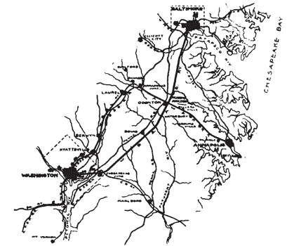 |
| Map Showing Route of the Washington, Baltimore & Annapolis Single-Phase Railway |
| |||
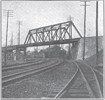
| Crossing Over Tracks of B. & O. at Baltimore |
The second portion of the Washington, Baltimore & Annapolis Railway consists of a single-track road located practically at right angles to the main line and crossing it at Academy Junction, 15 ½ miles from the Baltimore terminus. This road is a converted steam line and was formerly known under the name of the Annapolis, Washington & Baltimore Railroad. Incidentally this road is one of the oldest railroads in the country, having been built about 1835. It has now been electrified between Annapolis Junction and Annapolis with the single-phase system. The road connects at Laurel with the Berwyn & Laurel Electric Railway, a direct-current line, by which passengers can travel by the Washington Railway & Electric Company's cars to the Treasury Building in Washington. The Washington, Baltimore & Annapolis Railway proposes in the future to complete the system by equipping all of the Annapolis, Washington & Baltimore Railway, including the section shown by dotted lines in the map, so as to give an alternate route from Academy Junction to Washington.
| |||
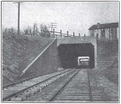
| Tunnels Approaching Baltimore |
The total mileage of the system, measured as single track, is 96.33 miles, divided as follows:
Main Line ..... 67.28 miles
A. W. & B. .... 20.5 miles
Berwyn & Laurel .... 8.55 miles
Total ....... 96.33 miles
This is exclusive of the Washington Railway & Electric Company's tracks from Berwyn into Washington, and of the tracks of the Columbia line from the District of Columbia line to 15th and H streets.
FARES AND SCHEDULES
The two steam railroads now connecting Baltimore and Washington are the Pennsylvania and the Baltimore & Ohio. The fare charged by both of these companies is for a single trip with no reduction for an excursion ticket except on Saturdays and Sundays, when an excursion ticket is sold for .25, good up to Sunday night. The time taken by the trains from terminal to terminal is about an hour, although a few trains make the run in a shorter time. The extent of the traffic is indicated by the fact that 123 trains a day are operated between the two cities.
| |||
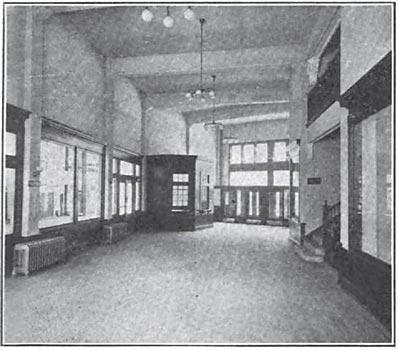
| Waiting Room in Baltimore Terminal Station |
| |||
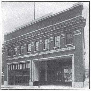
| Exterior of Terminal Station at Baltimore |
The electric railway company has decided to establish a fare of 75 cents for a single trip and .25 for the round trip, the return coupon being good at any time. This will include a transfer on the lines of the Washington Railway & Electric Company. The running time decided upon is one hour from terminal to terminal, that is from the corner of Liberty and Marion Streets in Baltimore to Fifteenth and H Streets, N. E., in Washington. The traveler would require about 15 minutes more to make the trip by the local cars in Washington to the Treasury Building, making the through time from the retail center of Baltimore to the Treasury Building in Washington about the same as by the steam railroad between these two points. It is proposed to commence with a headway of about 3o minutes, to be decreased as the needs of the traffic require.
| |||
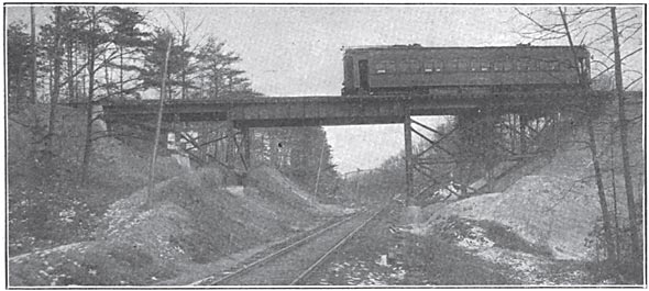
| Trestle Across Pope's Creek Branch |
The service between Annapolis and Baltimore and that between Annapolis and Washington will be by way of Academy Junction. The present fare by steam train from Annapolis to either of these cities is .20 one way and for the round trip. The fare on the electric line from Annapolis to Washington has been fixed at 75 cents for a single trip and .25 for the round trip, the distance being practically the same as that from Baltimore to Washington by the electric line. The fare between Baltimore and Annapolis has not yet been decided upon.
| |||
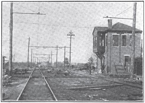
| Academy Junction, Showing Signal Tower |
| |||
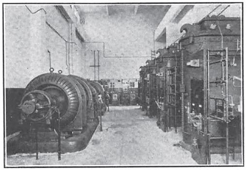
| Substation at Academy Junction |
ORGANIZATION
The Washington, Baltimore & Annapolis Electric Railway Company has a capital stock of ,000,000, which is owned largely in Cleveland. The officers of the company are: President, George T. Bishop; first vice-president, John Sherwin; second vice-president and general manager, J. N. Shannahan; treasurer and assistant secretary, C. F. Gladfelter; secretary and assistant treasurer, W. A. Kappler. The engineers in charge of the design and construction of the line are the Roberts & Abbott Company, of Cleveland. M. A. Munn has been chief civil engineer, J. C. Gillette engineer of line work and Bret Harter engineer of rolling stock. Simonson & Pietsch were architects for the Baltimore and Washington terminal buildings and for the local stations. The contractors for the greater part of the grading, track laying and line work were the Fidelity Construction Company, of Detroit, although Arnold & Wells did a part of the work.
THE PROBLEM STATED
The plan of connecting Washington and Baltimore by a high-speed electric railway has been under consideration for ten years or more and was brought prominently before the American Institute of Electrical Engineers in 1902, when Mr. Lamme described the single-phase system at that time proposed for the line. During that and the following year considerable grading was done by the company then back of the project. The road afterwards passed into the hands of the present owners and the plans were changed in a number of particulars.
In many respects the situation presented in 1905, when the present owners and engineers took charge of the project, was most complicated. Although it seemed necessary to use the tracks of the local railway companies in each city a serious problem was presented owing to the fact that the gage of the Baltimore tracks is 5 ft. 4 1/2 ins., whereas that in Washington is 4 ft. 8 1/2 ins. In methods of electrical distribution the practice of the local companies in Washington and Baltimore also differ, as the system in Baltimore uses the usual rail return, whereas the downtown lines in Washington employ the conduit and the suburban lines the double overhead trolley. The use on the interurban section of the single-phase system meant, then, the equipment of the cars with motors and control capable of utilizing high-voltage a. c. and 500 volts d. c. It also necessitated current collectors for a single overhead wire with the usual city clearance, a double overhead trolley wire, underground conduit conductors and a single-phase catenary with interurban clearance.
·
·
[left out because too detailed]
·
·
[Missing text]
·
·
·
·
TERMINAL STATIONS
The terminal station in Baltimore is illustrated in two of the accompanying engravings. The cars pass through the building which is provided with a waiting room on the ground floor and office rooms above. The company has also erected terminal stations in Washington and in Annapolis.
CATENARY CONSTRUCTION
Single catenary construction is used exclusively on the single-phase or interurban portions of the route. Although the poles along the double-track portion of the route are placed in pairs across the tracks, the side-bracket arrangement is employed throughout. The bracket adopted is the Ohio Brass T form, 2 1/4 ins. x 2 1/4 ins. and 11 ft. long. The bracket is secured in lugs on the poles and is held in position by a single iron rod braced from near the top of the pole. Where the track is double the two brackets on opposite sides of the track are tied together by an iron-wire cable containing a 24-in. wooden strain insulator at the center. This insulator has been inserted to insure safety to linemen when working with the wire over one track while the other is in use. All poles are guyed back with 24-in. wood strain insulators and Miller anchors so that the completed structure possessed great rigidity as to location, but the contact wire provides considerable element of flexibility by reason of the catenary suspension.
| |||
| View of Tangent, Showing Overhead Construction and Method of Tying Brackets Together |
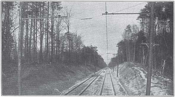
The poles are spaced 150 ft. apart except on curves of more than 6 degs. and are painted with carbolineum. The messenger cable is 3/8 in. in diameter and of high strength steel. The trolley wire is No. 0000. Hangers, on straight line, are spaced 16 ft. 8 ins., which, with a 150-ft. span, gives nine hangers to the span. A half-turn gripping arrangement on the top of the hanger, combined with a clamping device at the bottom, allowed the hangers to be placed with great rapidity. In fact by the use of four platform box cars as much as 4 miles of line has been erected in a single day.
The trolley wire on the main line is carried at a height of 19 ft. 6 ins. above the head of the rails, but on the A., W. & B. branch this height has been increased to 21 ft. on account of the freight traffic. The messenger insulators are of the double cloaked brown porcelain type. The upper surface of the top petticoat is molded with four grooves at right angles, so that if an insulator is struck with a stone or otherwise it will break along the groove instead of through the insulator. At overhead bridges the supporting insulators with the messenger wire is surrounded by an iron trough which is permanently connected to earth.
The General Electric Company supplied the hangers and insulators for the messenger cables, the steady braces and the section insulators. The Ohio Brass Company furnished the brackets and the high voltage transmission insulators.
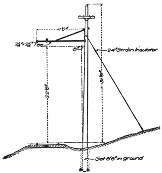 |
| Method of Guying Pole |
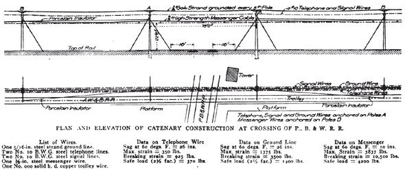 |
| Plan and Elevation of Catenary Construction at Crossing of P., B. & W. R. R. |
TROLLEY CONSTRUCTION
On the direct-current sections the trolley wire is suspended in the usual way except that the authorities in Annapolis required the company to install a double trolley system. The construction in Baltimore calls for no special mention except to say that the feed wire is carried on the cross-span between the two trolley wires. The local system in Annapolis is somewhat in the shape of the figure 9. On the tail of the 9 only three wires are used, the inside wire being negative and the outside wires positive.
| |||
| Section Insulators at District Line in Washington Where the Single-Phase System Connects With the Double Trolley Direct-Current System. |
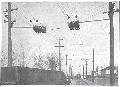
The junctions of the low and high tension systems of course required special installation. Here an insulated section a few hundred feet in length has been provided in the overhead system so that cars may pass from one to the other without drawing down the trolley poles. This section can be connected to either the high or the low voltage by a manually operated switch which is kept locked so that it can be thrown only by an employee. Later it is proposed to throw these switches from a signal tower. Each section insulator so employed is provided with an inner insulating runner which serves for guiding a wheel trolley, and two outer runners which were provided for use in case a pantograph is adopted later.
TELEPHONE AND OTHER CONDUCTORS
The railway company maintains its own telephone circuit. The telephone wires and the signal wires on the Annapolis branch are carried on a cross arm below the bracket. To provide against induction in the telephone wires the latter are transposed every five poles with single-pin transposition. Every precaution is taken to insure that a person using the telephone shall not be injured in case the telephone wire should come in contact with the trolley wire, or a low resistance path should be formed between the two. The telephone insulators are of brown porcelain 3 ins. x 3 1/8 ins., and the circuit is insulated for a working voltage of 6000. There is no direct metallic connection between the telephone instruments and the telephone lines. Each instrument is inductively associated with the line, an insulating transformer designed to withstand 25,000 volts between coils being used for this purpose. The central e. m. f. point of both the line side and the instrument side of each transformer is permanently grounded, so that all danger of a potential rise at the instruments has been eliminated. Kellogg bridging phones are used with a 2000-ohm ringer and a 5-bar generator.
At the top of the poles a No. 10 steel wire, grounded at each fifth pole, is carried for lightning protection.
BLOCK SIGNALS
The Annapolis single track branch is equipped with Blake manually operated block signals, made by the Blake Signal & Manufacturing Company, of Boston. The crossing at the Academy Junction is protected by a block signal system installed by the General Railway Signal Company and operated from a tower. The railway company has not yet selected the block signal system to be used on the main line.
CARS
The company has 24 cars built by the Niles Car Manufacturing Company. These cars were fully described in the STREET RAILWAY JOURNAL for October 12, 1907, so that no particulars of the bodies need be given here. A number of the features of the equipment. however, were not mentioned in that article and will be described.
TROLLEYS
One of the most interesting parts of the car equipment is the arrangement of trolleys, of which there are four to each car, two for each direction of running. It is quite probable that later a pantograph may be used on the single-phase sections, but up to the present no difficulty has been
·
·
[uninteresting details]
·
·
[Missing text]
·
·
