[Trade Journal]
Publication: Street Railway Journal
New York, NY, United States
vol. 30, no. 10, p. 360-361, col. 1-2
CATENARY CONSTRUCTION ON WASHINGTON, BALTIMORE & ANNAPOLIS RAILWAY
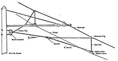
Several articles in this paper have described the preliminary work on the Washington, Baltimore & Annapolis single-phase railway now being constructed between those two cities. The work is now far enough advanced to give some details of the overhead line construction, which is of the catenary type. The road is double tracked from Washington to Baltimore, and a pole line is being erected on each side of the right of way carrying the brackets for suspending the trolley wires. The poles are placed 150 feet apart. The type of bracket used on this section of the line is shown in Fig. 1. These brackets are of T-bar construction 10 ft. 6 ins. in length with 5/8 in. supporting rod. At the outer end of each bracket is a guide casting, through which is threaded a cable extending across the track between each pair of poles. This cable is extended from each pole obliquely to the ground and there anchored with Miller guy anchors. This gives ample stiffening against lateral vibration. On the single-track branch line extending from Academy Junction to Annapolis a single pole line is used with the type of bracket shown in Fig. 2. These brackets are likewise of T-bar construction and are 11 ft. in length.
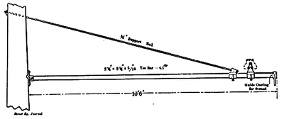 |
| Fig. 1. Bracket Used on Double-Track Line From Washington to Baltimore. |
 |
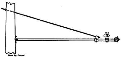
| Fig. 3. Showing Bridle Construction for Guying Trolley Wire and Messenger on Curves. |
All pole lines are grounded in the following manner: A ground line of 5/16 in. galvanized steel strand is strung along the tops of the poles, and this line is grounded at every fifth pole. On each pole at the back of the pole casting, and in electrical contact with the latter, is mounted a ground plate which is connected by a wire with the ground line carried along the tops of the poles. By this arrangement each bracket is thoroughly grounded. The messenger wire for supporting the trolley is carried on porcelain insulators mounted on malleable-iron pins with portland cement, the pins being adjustable on the bracket arms.
 |
| Fig. 2 Bracket Used on Single-Track Line From Academy Junction to Annapolis. |
On curves the poles are spaced closer, as conditions demand. Here the messenger and trolley are guyed to conform to the curve by wires extending from a porcelain strain insulator, mounted on the pole out to the nearest suspension rod and on each side of the bracket shown in Fig. 3 Fig. 4 shows the strain insulator used.
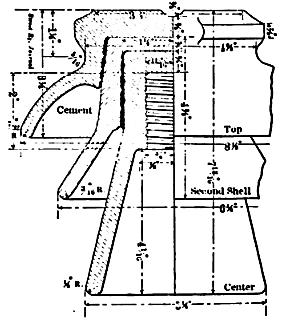 |
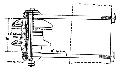
| Fig. 5. 33,000-Volt High-Tension Insulator |
The 33,000-volt insulators for the transmission line, the low-tension insulator for the trolley feeders and the telephone insulators are all mounted on the pole lines supporting the trolley wire. Fig. 5 shows the type of 33,000-volt insulator used. This insulator is of triple petticoat construction, the three members being cemented together. The maximum diameter is 9 3/8 ins., and the height over all 7 13/16 ins. The insulators are supported on 9-in. oak pins.
 |
| Fig. 4. Strain Insulator Used on Curves Radial Gear. |
The material described including the Detroit trolley wire clamps, the Miller guy anchors and other accessories was furnished by the Ohio Brass Foundry.
