[Trade Journal]
Publication: The Electrical Engineer
New York, NY, United States
vol. 24, no. 493, p. 341-345, col. 1-2
ELECTRIC TRANSPORTATION.
A HIGH SPEED ROAD. THE LORAIN AND CLEVELAND
ELECTRIC RAILWAY.
BY B. P. ROBERTS.
THE first of October will see the opening of one of the most completely equipped and thoroughly constructed electric lines In the country. Of the many lines converging at Cleveland from the suburbs, it will stand alone as an example of the most modern practice.
| |||
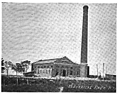
| Power House, Lorain & Cleveland R. R. |
Starting from the Public Square, the cars will run over existing city limits 8 1/2 miles to Rocky River, through business and residence districts, part of the distance being through the hamlet of Lakewood. After crossing the beautiful gorge of Rocky River the road leaves the highway, and from this point the company owns its own right of way. This extends practically parallel to the shore line of the lake, a distance of 18 1/2 miles, to Lorain, a growing city of about 12,000 inhabitants.
| |||
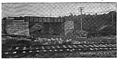
| Double-Track Girder Span Over L. & C. R. R. Tracks. |
It is to open up a region of country that has, strangely, never before been accessible except after a tedious journey, and will give miles of lake front advantages for summer homes and suburban resorts.
THE ROADBED.
The company has spared no pains to make the roadbed equal to the best steam road practice. The curves are few and the sharpest one on the main line is only a 4 deg. curve, equivalent to a radius of 1,430 feet. The grades are hardly worth mentioning, being for the most part only about 20 feet to the mile, and the steepest one, if it may be so designated, 40 feet to the mile. Embankments are made 14 feet wide and cuts 18 feet, slopes being 1 1/2 to 1. Gravel ballast is used. The ties are 6x8 in. x 8 feet, 2,640 to the mile.
The rails are in 60-foot lengths; T rails, 70 pounds per yard, American Society of Civil Engineers standard pattern. They were rolled at the Edgar Thomson Steel Works. They are laid with suspended joints, using heavy angle bars. The nuts are secured with the National nut lock, and are inside the rails, Instead of outside, as in current practice, to facilitate inspection by the track walker.
| |||
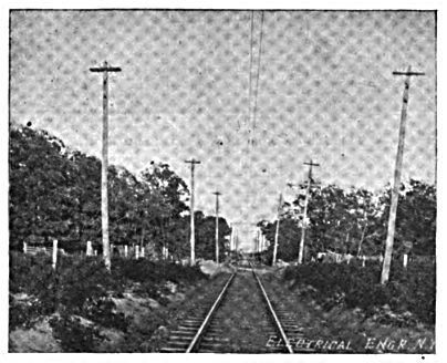
| Track and Line Construction, Lorain & Cleveland R. R. |
The road is single track, except at the Rocky River end. where, through the village, the curves are sharper and closer together, and to secure safety and speed there is about one mile of double track. There are three passing sidings, each 1,500 feet long, besides a long switch, at Avon Beach Park, where the spur to the power house is taken off, and a Y and switch at the Lorain terminal.
The road passes under the Nickel Plate right of way, which at this point is carried over on a double track plate girder, having a span of 55 feet, shown in one of the accompanying engravings.
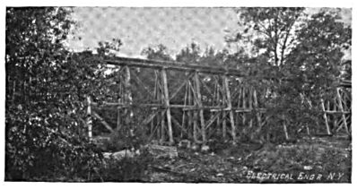
There are four trestles on the line, the longest being 576 feet in length, and 40 feet high. Smaller openings are spanned with I beams. Masonry foundations are used under all these structures.
| |||
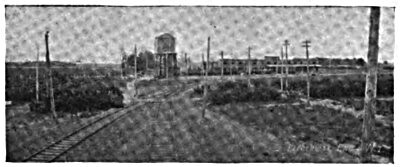
| Avon Beach Park Station and Car House, Lorain & Cleveland R. R. |
The right of way for the entire distance is from 40 to 60 feet wide, and is enclosed by wire fence made by the Page Woven Wire Fencing Company, of Adrian, Mich. All special track work was done by the Cleveland Frog and Crossing Company.
THE LINE CONSTRUCTION.
The line construction is also very substantial. Overhead frogs are avoided by the use of the double trolley system. The trolley wire is Washburn & Moen's figure 8 wire, equivalent to No. 000. The hangers and other overhead material, other than wire, were furnished by the Ohio Brass Company. Thirty-five foot poles are used in a double line for cross suspension. The feeders are 300,000 c. m. solid there being three going each way from the power house at present. Carton lightning arresters are used on tlie lines.
THE ROLLING STOCK.
The cars are J. G. Brill & Co.'s standard 41 feet double truck.' They are equipped with 4 50 h. p. General Electric motors and controllers and these are expected to give a very rapid acceleration in starting. Electric brakes are also provided.
| |||
| Trestle on Lorain & Cleveland R. R. |
The run to Rock River is made in 40 minutes and from there to Lorain, 18 1/2 miles, in 35 to 40 minutes, or about 30 miles per hour, running time, which, with frequent stops, requires a speed to be attained of 45 to 50 miles per hour.
THE OFFICES AND CAR BARNS.
The superintendent's office and operating offices are located in a handsome brick structure, 200 feet by 65 feet, at Avon Beach Park. In the same building are the car barns, repair shops and waiting rooms. This point of the road is destined to be the operating center, as north of the offices and car barns the company owns 20 acres fronting on the lake, which will be converted into a park, and in which is located the power house, from which all the power used on the line is taken. This park is 12 1/4 miles from Rocky River, and will undoubtedly prove an attractive resort.
The water supply for the entire settlement is obtained through a 24-iuch intake pipe, which, because of shallow water, had to be extended 1,200 feet into the lake to avoid trouble from anchor ice. This pipe supplies water to a large "cold well" just outside the power house on the shore, and the supply for all uses is obtained from this well and pumped into a 50,000-gallon tank through an 8-inch pipe. From this tank 6-inch mains supply the car house and the settlement around the park.
The plans of the company have been to allow for future extension in every way, and this is especially noticeable in the case of the power house.
THE POWER HOUSE.
As the car service is intended for high speed and rapid acceleration, the fluctuations of load are very great and momentarily even 100 per cent, in excess of the rated capacity of the generators. The power house was made large enough to include space for an engine and generator of twice the capacity of those now installed and the stack was made to accommodate even a still further addition if it should ever be necessary. The engines, steam piping, and generators now in place, are designed to stand a steady 50 per cent, overload, or even 100 per cent, momentarily.
The ground level being 22 feet above the lake, the boiler room was excavated, as shown in the cross section. The material obtained was used partly in making the embankment, on which the coal cars are elevated the necessary 12 feet to run in over the coal storage tank in the boiler room, and partly to till in on the shore and keep the wave action from undermining the bluff. This arrangement allows the condensers to stand on the lower or boiler room level, which is only six feet above the lake level. This distance may increase, however, to 8 feet in case of low water.
The coal is dropped through suitable gratings from the cars into the coal storage tank, which extends the entire length of the building, and some 30 feet extra. From this tank chutes extend to the magazines of the Murphy stokers. These chutes are hung like the platform of a scale and the coal, after being run in, is weighed before it is allowed to drop into the magazines. This arrangement entirely dispenses with all handling of eoal. and at the same time an accurate record can be kept of just how much is required each day.
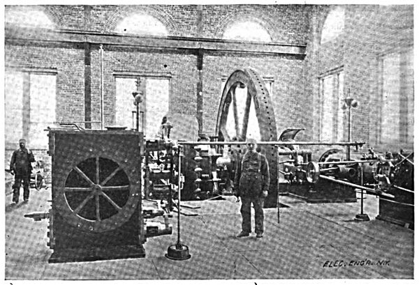
| |||
| A Corner of the Engine and Dynamo Room, Lorain & Cleveland R. R. |
The boiler room contains two batteries of Sterling boilers, each battery having two 300 h. p. boilers. These are equipped with Murphy stokers. Space is left in the boiler room for 900 h. p. more when required, which will make a total boiler capacity of 2,100 h. p. These boilers are capable of carrying 150 pounds, or even 175 pounds of steam, although the plant at present is running with 135 pounds pressure.
THE ENGINES AND GENERATORS.
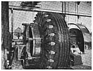
The engine room at present contains two cross compound Corliss engines made by the C. & G. Cooper Company, of Mt. Veruon. O. The cylinders are 20x36x48 inches and the engines run 80 revolutions per minute. They have 20-foot fly wheels, weighing 60,000 pounds each. Direct connected to these engines are two 400 k. w. Siemens & Halske railway generators, wound for 630 volts at no load to 700 volts at full load.
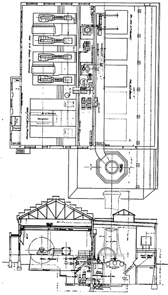 |
| The Lorain & Cleveland R. R. Plan and Section of Power House. E. P. Roberts & Co., Consulting Engineers. |
The appearance of these units is shown in the engravings. The steam piping is carried to and from the engines under the floor, iron plates being provided for accessibility between the cylinders. This arrangement is preferable on account of the travelling crane, as well as because of the location of the boiler room 22 feet below the engine room floor.
Between the engine foundations and the fireproof middle wall is the pump pit, containing the pumps and the bulk of the piping. In this pit are vital features of the plant, and the whole arrangement is so planned by duplication and by-passiing that no ordinary accident can possibly cripple the running capacity of hte plant.
A wing is extended from the southwestern corner of the plant and this contains the switchboard, a coat room and wash room, and a small work room. Sub-foundations are put in for the addition of one 800 k. w. unit in the future.
The engines are fitted with double eccentrics on both high and low press cylinders, and have each two governors, one to operate the release valves and the other to release a weight which operates a butterfly valve In the steam pipe, cutting off the supply of steam when the engine increases speed more than 10 or 12 per cent. The falling of this weight throws a circuit breaker in the main generator circuit, so that thu whole apparatus will come to a standstill.
THE STEAM PIPING, PUMPS, ETC.
The steam piping is arranged to run in several ways, either condensing or non-condensing, with either or both cylinders using direct steam; that for the low pressure cylinder passing through a reducing valve.
| |||
| Siemens & Halske Generator, Loraine & Cleveland R. R. |
There is a complete oiling system for both cylinder and lubricating oil, the oil being fed into the lines from tanks located in the boiler room. Lubricating oil drips are carried to an oil filter in the basement and pumped into the tanks again. The cylinder oil is separated, as far as possible, in a reservoir, and automatically collected for further use. A Musgrave column is used in connection with the sight feed lubricators for the cylinders. Hand pumps are also provided. The butterfly valve also has a small hand pump. The main steam valves are controlled by floor stand wheels.
There are, for each engine, the necessary gauges, 12 inches in diameter, mounted on enamelled slate boards, resting on pedestals. There is also a main gauge board on the middle wall, which has in addition to the usual instruments an 8-day clock and a Bristol recording gauge.
In the pump pit are located two Blake twin vertical air pumps, 10x22x15 inches. It is intended that normally each condenser shall operate with its own engine, but a cross connection is provided so that either condenser may be used for either or both engines. A small Blake low-service pump takes water from the hot well and delivers it to a Stilwell vertical open heater. From here it is pumped into the feed water main by one of two Blake duplex outside packed plunger pumps.
The supply of water from the feed water main to each boiler is regulated by Thomas governors.
All the pumps are controlled by Fisher governors. The service pump is located between the air pumps and furnishes ample water supply for the entire settlement. It can be operated also as a fire pump, and is ready to throw three 1 7/8-inch fire streams at a moment's notice. There are at present three Ludlow 2-nozzle hydrants in the system.
The high pressure piping is all extra heavy flanged, with tongue and groove joints. Copper gaskets are used. The covering is Keasbey & Mattison's magnesia sectional covering. The low pressure piping is standard weight, covered with magnabestos. The valves for high pressure are Crane's extra heavy bronze seated, the larger ones being by-passed. The angle and globe valves, are of the Jenkins type.
The intake and overflow pipes are cast iron, 20 inches in diameter, and lie in a trench below the floor in the boiler room under the breeching. The intake, or injection pipe supplies the condensers, and takes its supply from the cold well. The discharge and blow-off pipes run into the lake.
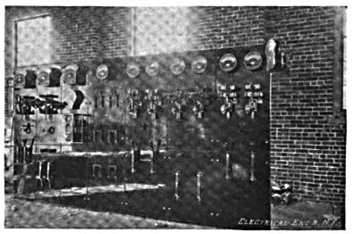
THE SWITCHBOARD.
The switchboard is of enameled slate and is equipped with the usual instruments, including a Weston illuminated dial ammeter for each generator, and one for the total out-put, six Weston round dial ammeters for the feeders, a Weston illuminated dial voltmeter for the bus-bars, and a Weston illuminated dial differential voltmeter to be used for throwing the generators in multiple. There are also a Bristol recording voltmeter, and a General Electric recording ammeter. Special provision is made in the matter of ground wires to track and water pipes.
An even illumination of the switchboard is obtained by lighting it from above, similar to the scheme used for lighting pictures in art galleries. The setting of the switchboard flush with the wall with plenty of room behind it, as well as plenty of light, is a plan that recommends itself at once, especially where a traveling crane is used.
The bus-bars on the board are so designed that additional strips can be added when the additional generator is installed. The board has also six feeder circuits in three panels and a lighting panel, in addition to the generator panels. The lighting panel has several circuits, one each to the car house and grounds, as well as the one in the power house.
THE BUILDING.
It will be noticed that the building is something more than a mere shed. It is architecturally pleasing, and the 200-foot stack is also an excellent piece of construction. Both these are very substantially built and fireproof throughout The boiler room floor is cement and the engine room floor is also cement, supported by hollow arch tile and steel beams. Large openings are left in the engine room floor over the condensers, through which a view of the pump pit can be had. There is also an opening for stairway from below. In the boiler room a light bridge connects the engine room with the top of the coal tank, steps being led down to the top of the boilers and the top of the Murphy stokers. Galleries run along the piping in the pump pit and over the boilers for easy access to all valves.
The 15-ton traveling crane was furnished by the Cleveland Punch & Shear Works, and has two 8-ton trolleys, with triplex blocks. The span is 54 feet 6 inches. The crane has roller bearings throughout and cut gearing.
OFFICERS AND CONTRACTORS.
The officers of the company are: B. Mahler, president; E. G. Tillottson, vice-president; E. W. Moore, treasurer; J. C. Hoge. secretary; F. W. Coen, assistant secretary; W. E. Davies, superintendent.
One of the prominent members of the company is Mr. C. W. Wason, who is well known to electric railroad men, not only because of his connection with Cleveland roads, but because of his interests in other cities. Mr. Wason acted as general consulting engineer for the entire work. Mr. A. P. Ruggles acted as chief engineer for the road. The power house was intrusted to E. P. Roberts & Co., consulting engineers. Mr. J. N. Richardson was retained by E. P. Roberts : & Co. as architect for the power house, and afterward by the company for the car house.
| |||
| Switchboard, Lorain & Cleveland R. R. |
The iron and steel work in the power house was designed by the Osborne Company, who also had charge of the inspection of all iron and steel for the road and that used in the boilers.
The Chase Construction Company, of Detroit, were the contractors for the line work. L. Dawtel was mason contractor for power house and car house. J. W. Vanderwerf was contractor for woodwork for power house and car house. The Forest City Wire and Iron Company were contractors for structural steel in both power house and car house. Messrs. Chafer & Becker were contractors for all steam and water piping and the water tank.
