[Trade Journal]
Publication: Electrical World and Engineer
New York, NY, United States
vol. 35, no. 15, p. 545-547, col. 2, 1-2, 1
Power Transmission Schemes at Duluth, Minnesota.
By FRANK W. SPRINGER.
THE water-shed of western Lake Superior, as shown by the map, Fig. 1, is not a greater area than that included within a circle of fifty miles radius, drawn with Duluth as a centre. At the circumference of the circle this water-shed is from 600 to 1200 feet above the lake level. The bluffs on the north shore at Duluth vary in height from 500 to 800 feet, while the south shore is mostly lowland. The two rivers to be considered in this article, the Black River on the south and the St Louis River on the west and north, have cut these bluffs back for a distance of about fifteen miles, measured in a straight line from Duluth. At these points are found rapids and falls of considerable height, while above and below both rivers arc comparatively smooth. Of the St. Louis as a water power, the following may be said:
 |
| Fig. 1. Water Shed of Western Lake Superior. |
It drains an area of 38,000 square miles composed of pine land, swamps. lakes and some arable land. The rainfall may be given as thirty inches per annum. There are two periods of low water. One is due to the summer drouth [sic] drought and the second is caused by the freezing of the small streams and swamps, many of which freeze solid. The minimum flow occurs in winter, when the power may be estimate at 15,000-hp at a head of 600 feet. The problem has been to augment this minimum flow. It is safe to say that very close to a million dollars have been spent in preliminary surveys, options, etc. In fact, the water power of the St. Louis River has come to be such a joke on account of the innumerable unrealized projects to utilize it, that it is difficult for anyone outside of Duluth to take it seriously. Of the many schemes proposed by some of the best engineers of the country, the following are taken as most striking:
1. A dam from 80 to 100 feet high to be built above the town of Cloquet. This would give a reservoir 60 miles long by one mile in width, submerge a railroad which has been built in the river valley, also a part of an Indian reservation, and, worst of all, be a constant menace 10 the town.
2. Dam the outlets of the larger lakes which constitute the principle sources of the river. These dams would need to be but a few feet in height.
3. The adjoining water-shed on the north is about 60 per cent. as large as that of the St. Louis. At one point the headwaters have the same source. A dam 20 feet high and a channel 12 miles through a swamp would divert the adjoining waters into those of the St. Louis. Also a reservoir of 30 square miles and 10 feet deep could be established. From an engineering standpoint, this latter stems to be the most complete solution of the problem.
The falls and rapids of the river, embracing a head of about 400 feet, extend along the river for a distance of three miles, the nearest point of which is about 12 miles from Duluth. The riparian rights to this property are held by Mr. J. Cooke. With the understanding that Mr. Cooke would sell his interest for about $1,000,000, the Minnesota Canal Company was formed, and it was planned to build an open canal from Coquet to Duluth, a distance of 25 miles. Its object was twofold. In the first place, an income of $100,000 a year was expected for the use of the canal in floating logs to Duluth. On account of the falls it is now necessary to bring them by rail. In the second place, it was intended to construct a reservoir on the bluff above Duluth and from this point distribute water under a head of 600 feet to various power users. This company expected to develop over 100,000-hp. The high figure at which Mr. Cooke held his rights alone prevented this plan from being carried out. This company is said to have expended $300,000. These dreams were indulged in and paid for before long-distance transmission by electricity had become practicable.
Lately, another St. Louis power development company has been formed It has acquired the rights necessary, and seems to have every prospect of utilizing a part at least of the St. Louis water power. A canal is to be built from a point above the rapids for a distance of three or four miles down the river. From this, 800 feet of pipe line will be run to the power house, placed in the bed of the stream. This will give a head of over 350 feet, or something like 10,000-hp net at minimum flow. The power thus obtained will be transmitted to Duluth by the use of polyphase generators, step-up transformers, etc. As the demand for power increases, dams will be built at the outlets of the various lakes and small streams which constitute the sources of the river, in order to tide over the minimum flow periods, and the power house capacity increased.
The country through which the lilac Black River flows and the climatic conditions arc the same as those of the St. Louis River. The average rainfall for the past eight years is 26.64 inches, and for the last 30 years 33.01 inches. The decrease is probably due to cutting off the timber. A large part of the rain falling in this region is brought by northeast winds front Lake Superior. The reason that this power has not been considered before is that it was wholly unavailable until the application of long-distance transmission by electricity became practical. A company known as the Black River Tails Company has been formed, 1000 acres of land purchased, which gives complete control of the water power, and plans outlined to transmit the power to Duluth and Superior. In fact, it is simply a question of marketing the power which delays actual construction.
| |||
| Fig. 2. Lower Falls of Black River. |
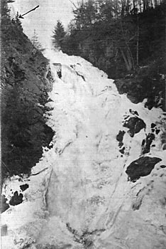
Owing to favorable conditions, it is estimated that it will not cost more than $55 per horse power to distribute this power in Duluth and Superior. As will be seen below, the storage necessary to take care of the minimum flow can be obtained at a comparatively low cost. At present the minimum flow is said to be 3500 cu. ft per minute. The upper falls have a height of 35 feet. A masonry dam 20 feet high will be built across the gorge at the head of these falls, making a total head of 55 feet, and giving a flowage of 6,000,000 cu. ft. The cost of this structure will not exceed $5500.
The lower falls (Fig. 2) are located 4000 ft. below, and are much higher than the upper falls. The power house, 50 feet by 70 feet long, will be placed in the bed of the stream at a point 7200 feet below the upper falls, a steel pipe line 54 inches in diameter being run from the dam across country to the Pelton water wheels in the power house. The pipe line is to be buried to prevent freezing. As the total head is 330 feet, the lower half of the pipe will be made of ½-inch steel plate.
The source of Black River is a lake of the same name, with an area of about 300 acres. A dam 10 feet high and 100 feet long, built one-half mile below the lake, will raise the lake four feet, increase its size to 900 acres, and give a total flowage of 210,000,000 cu. ft. The dam can be constructed of logs at a cost of $4000.
A second dam of similar construction, 500 feet long, costing $5000, and located in a gorge 10 miles below the lake, would give a storage of 50,000,000 cu. ft, and a third dam, 35 feet high, 300 feet long on top, costing $6000, built at a point 10 miles below the second, would increase the flowage another 50,000,000 cu. ft.
 |
| Fig. 3. Plan of Power House. |
Two direct-connected polyphase 800-kw generators are to be installed, together with five (one reserve) oil transformers, raising the pressure from 440 to 18,000 volts. A similar set of transformers will be used at the receiving end. The pole line will consist of 35-foot cedar poles, eight inches at the top, and set 52 to the mile, with 3-pin cross-arms and 24-inch spacing, and No. 1 bare copper wire, mounted on three-part Locke insulators.
| |||
| Fig. 4. Log Dam on Black River. |
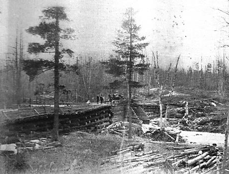
Fig. 3 shows the general plan of the power house. A release valve is placed at B on each one of the intake pipes. R is a heavy wall separating the dynamo room from the pipe line, protecting the machines in case of a break in the pipes. Fig. 4 is a view of a log dam used by lumbermen in floating their timber down the Black River. It shows very well the general character of the country of northern Minnesota and Wisconsin.
With the prospect of the immediate development of two such powers as those of the Black and St. Louis Rivers, it looks as though what had long been hoped for by the people at the head of the lakes would soon come to passthat is, the beginning of the manufacture of iron and steel at Duluth and Superior.
