[Trade Journal]
Publication: The Electrical Engineer
New York, NY, United States
vol. 24, no. 480, p. 39-42, col. 1-2
POWER TRANSMISSION
THE POWER PLANT OF THE PIONEER ELECTRIC
POWER COMPANY OF OGDEN, UTAH.
IN the canon of the Ogden River, near the city of Ogden, Utah, the latest and most important hydraulic power plant of that State, and one of the largest works of the kind yet undertaken in this country has been carried out during the past year by the Pioneer Electric Power Company of Utah. The city of Ogden is situated in the basin of the Great Salt Lake, at an elevation of 4,300 feet above sea level about 13 miles east of that body of water, and 35 miles north of Salt Lake City. The city extends eastward to the base of the Wahsatch Mountains, which tower 5,000 feet higher, reaching a total altitude of fully 9,000 feet above sea level. This chain of mountains is intersected by numerous deep valleys or canons, forming the outlet for drainage areas of considerable extent. The outlet of the narrow canon of the Ogden River is east of Ogden and distant about two miles from the business center. At a point about six miles above its mouth the gorge widens out into a valley, some eight miles long and four miles wide, surrounded by an almost continuous mountain chain. This valley is traversed by three streams which unite at the upper end of the canon to form the Ogden River.
The average annual rainfall in Ogden is 14 inches. In the Ogden Valley it is probably twice as great. The drainage area is about 360 square miles. The flow of the river varies greatly in different years and at different seasons. In May and June, when the snow on the mountains melts, a maximum flow of 4,800 cubic feet per second has been measured, while a minimum of 80 cubic feet in August and September is also on record. The minimum in average years is fully 125 cubic feet per second. The slope of the stream in the upper valley is comparatively gradual, while in the six miles of the canon there is a total fall of nearly 500 feet. This portion of the river has long appeared an attractive Held for the development of power, but apart from a small saw-mill near its mouth there have been only abortive attempts made at utilizing the fall of the stream.
| |||
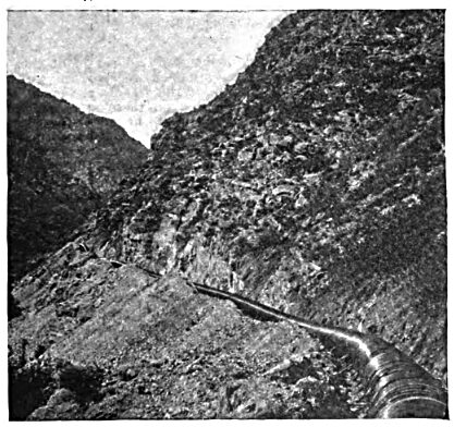
| Fig. 1 the Pipe Line Along the Side of the Canyon. |
The plans of the Pioneer Electric Power Company contemplate the utilization of the waters of the entire Ogden River water ghed above the mouth of the canon for the development of power as well as for irrigation. The central features of the plant are: A large storage reservoir and a masonry dam at the upper end of the canon; a pipe conduit 6 feet in diameter; a power house with water wheels and electric generators, electric transmission lines and substations for distributing the power to different points, and an extended system of irrigation canals.
| |||
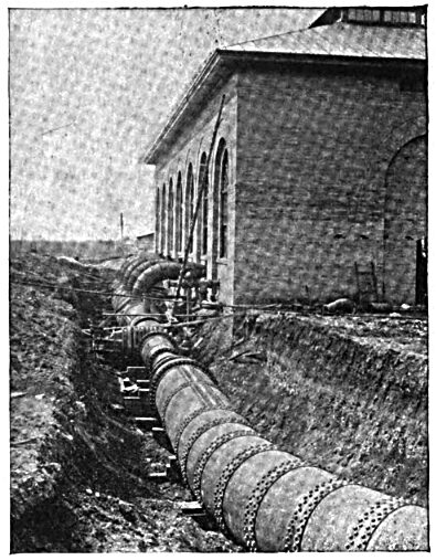
| Fig. 2 Exterior of Power House, Showing One Venturi Meter and Receiver. |
The storage reservoir will cover an area of about 2,000 acres, and will have a capacity of nearly 15,000,000,000 gallons. It is formed by building across the canon, a short distance below its upper end, a dam of concrete masonry built up of isolated piers and arches founded on bed rock. The length of the dam on its crest is about 400 feet it will have a total height of 100 feet, 60 feet of which will be above the level of the present river bed. The up-stream face is protected by a steel plate covering to prevent abrasion and percolation.
A 9-foot tunnel excavated through the solid rock around the south abutment of the dam forms the outlet for the water of the reservoir. At its upper end it connects to a masonry inlet tower, which is in turn connected by a riveted steel pipe 8 feet 6 inches in diameter with the main gate house, 100 feet below the tunnel. This contains two 72-inch valves, one controlling the supply of the main conduit, the other discharging the surplus water.
The main conduit is a pipe line 6 feet in internal diameter. Its total length is 31,600 feet, of which 27,000 feet is wooden stave pipe, and 4,600 feet at the lower end rivetted steel pipe. It is laid in a trench 8 1/2 feet wide, and covered with earth to a depth of 3 feet on top. The selection of smooth wooden stave pipe in lieu of steel pipe throughout, was made on account of the greater cheapness of the former, as well as its less internal resistance to the flow. The pipe is laid along the side of the canon and follows the mountains to a point about half a mile beyond the mouth of the canon. It is built to conform to a hydraulic grade line of 2 feet per thousand, a slope believed to correspond to the friction in the pipe. At the upper end of the pipe the inlet is funnel shaped, and the wooden pipe is continuous except at three points where two rivetted steel elbows and a short length of tunnel are substituted. There are eight tunnels in the rock, the longest being 667 feet. There are also eight steel bridges with a total length of 500 feet besides a timber trestle. The maximum hydrostatic head in the wooden pipe is 117 feet, giving a pressure of 50 pounds per square inch.
From the end of the wooden pipe the steel conduit runs to the power house. The slope of this is quite steep and the pressure is from 50 to 200 pounds per square inch. It is 60 feet in diameter until it readies a point 100 feet from the power house, where it divides into two branches, 54 inches in diameter, which lead to two receivers, one on each side of the power house. There are 13 elbows in this pipe, and its entire weight is over 2,500,000 pounds. The total efficient head from the flow line of the reservoir when it is full to the center of the reservoir is 446 feet.
Between the inlet tower at the dam and the power house there are five large gate valves, besides the smaller blow-off and relief valves. Three are 6 feet in diameter, the other two 42 inches. The first two of the larger ones weigh about 23,000 pounds each and are in the gate house; the third is placed near elbow No. 2 of the steel pipe line about 100 feet below its junction with the wooden pipe. Its purpose is to permit the closing of the wooden pipe to keep it full of water even when the steel pipe is empty. The head at this point is about 200 feet. The valve has only a single valve stem and is operated by a hydraulic lift supplied with pressure water from the main pipe above the valve. The total weight of this valve is 52,000 pounds, the heaviest single piece in it weighing about 20,000 pounds. Besides these large valves there are two smaller, each 24 inches in diameter. These are placed between the lower end of the 6-foot pipe and the power house in the 54-inch branches leading to the receivers. Those branches are reduced to 42 inches by the use of Venturi meters, thus permitting the use of the smaller valves, which are operated by hand. The pipe is fully provided with air, mud and relief valves. The connection between the main pipe and the branches is made by a breeches casting secured to the steel pipes by cast steel angle flanges and bolts. To withstand the great longitudinal pressure, a heavy concrete block is built around the casting. Of the nine bridges the longest Is that over the Ogden River. This is a rivetted bow string girder 75 feet long. The other bridges carry the pipe line over lateral ravines or were built in place of masonry retaining walls, where a steel structure was cheaper.
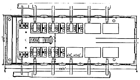 |
| Fig. 3 Plan of Power House. |
The power house is built of pressed brick, with concrete and rubble footings, and cut stone trimmings. Its outside dimensions are 135 feet in length by 50 feet in width. The roof trusses are of steel, and are supported on steel posts imbedded in the brick walls. A traveling crane of 15 tons capacity, operated by hand power, traverses the building, the track girders being carried by the steel posts. This building contains all the hydraulic and electric machinery used. A smaller, separate building serves as a machine and blacksmith shop.
The water is delivered from the pipe conduit into two receivers, buried in the ground, one at either side of the power house. They are 6 feet in diameter and, in their general appearance and the material used closely resemble the regular steel pipe conduit, the thickness of the metal, however, being increased to 7/8 inch in order to allow for the water hammer.
The receivers are provided with five safety valves each, which discharge when the pressure exceeds 200 pounds per square inch, and an outlet gate at the bottom. From each of these receivers, five 30-inch and one 10-inch, intake pipes extend to the walls of the power house to connect with the water wheel nozzle pipes. Between these intakes and the nozzle pipiot are placed the following valves in the order named: One 18-inch geared gate valve, one 18-inch hydraulic gate valve and one 18-inch butterfly valve.
The 18-inch geared gate valve is only to be used in case of repairs to the particular machines that govern it. The 18-inch hydraulic gate valve is piped up to a small D valve, which is placed back of the switchboard and under the floor. By means of a lever on the switchboard, connected to this D valve, the gate can be opened or closed at the operator's will. This valve is the one which is to be used for starting or stopping a wheel. The 18-inch butterfly valve is operated by means of a worm gear from the governor, and is used in checking the speed of the wheel by reducing the head or pressure near the nozzle and thus avoiding a sudden fall of head in the main pipe which would be detrimental to the proper working of the plant.
The nozzle for the water wheels has six rectangular openings or ports 111-16 x 3 1/2 inches in area, of which the operator is able to close one or more as he may desire. The levers that operate the hydraulic gate and nozzle are placed near the top of the switchboard. The set of levers for each water wheel is placed in the panel governing the generator which is driven by the wheel in question, so that the operations required in starting or stopping these machines are reduced to a minimum. The wheels are of the impulse type directly connected to the generators. The complete plant will consist of ten units, five being already installed. The power house and receivers being built for the ten, the balance can be readily installed at any time.
The Knight water wheels are 59 inches in diameter and have 45 bronze buckets east in one solid piece; 14 of these will, when the nozzle ports are all open, receive the water at. tlie same instant. The centers of the wheels are made of cast steel, the buckets being pressed on these steel centers and secured with bolts. These wheels are keyed to the generator shaft. Each wheel has a capacity of 1,200 horse-power at 300 revolutions per minute, and each is provided with two flywheels, about 70 inches in diameter, each weighing about two tons.
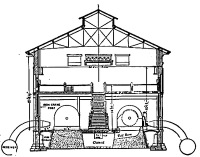 |
| Fig. 4 Section of Power House. |
The armature, armature shaft, two fly-wheels and one water wheel, which comprise the moving parts, weigh 15 tons. This allows a uniform speed to be maintained notwithstanding changes of head in the main pipe, or changes in the generator load. The water wheel, fly wheels, nozzle and the two hydraulic cylinders controlling the nozzle ports are encased in a steel housing, bolted to the machine bed frame.
Between the two lines of machines and down through the center of the building underneath tlie concrete floor is the spillway into which the wheels discharge the water, and through which the water is carried back to the river from which it is taken.
The generators used in this plant are of the General Electric Company three-phase type, with 24 poles, and at 300 revolutions per minute, have an output of 750 kilowatt at 2,300 volts, and a frequency of 60 cycles per second. The factory tests show that the variation in volts will be less than 5 per cent, with a constant speed, should the full non-inductive load bo thrown off or on.
Between the machine foundations and the building foundation wall, on each side of the building, is a subway which runs the entire length of the building and across the rear, and in this subway are carried all the necessary piping for water wheel controllers and all the wires between the generators and tlie switchboards. The cable connecting each generator to its respective panel on the generator switchboard is a three-wire concentric 250,000 C. M. lead-covered cable, and the exciting wires are a two-wire concentric No. 4 B and S lead-covered cable.
The exciters used on this plant are G. E. six-pole 500 volt machines, and will give 100 kilowatt at 550 revolutions per minute. Each of these machines is ample for the entire exciting current that will be needed for the ten 750 kilowatt alternators, and they are each direct connected to a 135 horsepower Knight water wheel, similar to the 1,200 horse-power water wheels previously described. These exciter water wheels are cross-connected to each receiver, so that either exciter can be operated from either receiver.
The generator switchboard consists of seven marble panels; five for the alternators, one for the exciter and one for the instrument panel.
These panels are 26 x 90 inches each. They are built up of blue Vermont marble, with nickel fittings. There are two sets of three-phase bus bars oft the back extending the entire length of the seven panels, as well as two bus bars, also running their entire length, from which the exciting current is taken.
From the generator switchboard the current is carried to the distributing board over copper bars, of which there are two sets of three, connecting the two sets of bus bars on the generator board with the two sets of bus bars on the primary panels of the distributing boards.
| |||
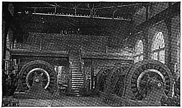
| Fig. 5. Interior of Power House. |
The distributing board is in a gallery in the rear of the building and over the generator switchboard. Back of this distributing switchboard are nine 250 kilowatt air blast stepup transformers, the lightning arresters, and the two blowers for cooling the transformers. The distributing board is divided into two sections the primary section and the secondary section.
Back of the distributing switchboard and on a raised platform are placed the step-up transformers. These transformers raise the potential of the current from 2,300 to 16,100 volts, at which pressure it goes on to the long distance transmission lines. The transformers are connected up in sets of three, the delta connection being used on both sides. At each end of the building in the gallery are placed the two blowers, direct connected to a 2 1/2 horse-power 500 volt direct current motor. These blowers are used in cooling the step-up transformers, and force the air up through the bottom of the transformers, around the coils and out at the top.
The transmission line is calculated to deliver about 3,000 horse-power at the sub-station in Salt Lake City, distant about 38 miles, and consists of two circuits, making six wires of No. 1 B and S gauge.
The poles used on this line are of Oregon cedar, and are good, clear, straight poles, 30, 40, 50 and 70 feet long, with 9-inch and 10-inch tops. There are two cross arms on each pole for the wire; two wires are on the top arm 4 feet apart, and four wires on the bottom arm, each 2 feet apart, a circuit being on each side of the pole. These wires are so arranged that should a plane be placed perpendicularly across the circuit it would show an equilateral triangle, with a wire at each angle, the length of the sides being 2 feet. These wires are transposed about every half mile. By this arrangement of the pole line wire, the inductive effect is reduced to a minimum.
About 6 feet below the second cross arm on the pole is a two-pin cross arm, on which the telephone wires are strung, being transposed about every four poles, there being an average of about 50 poles per mile.
The current is fed into the transmission line at the power plant at 16,100 volts and delivered to the step-down transformers at 13,800 volts. This will give an energy loss of about 10 per cent, in the line, and a potential loss of about 14 per cent. The substation step-down transformers deliver its current to the local distributing lines again at 2,300 volts. There are at present nine 250 kilowatt step-down transformers at the substation connected by the step-up transformers, and the switchboard in the substation is similar in every respect to the distributing board in the power plant gallery. The cooling apparatus here is also identical with that used in the power plant, except that the motors used are 60 cycle induction motors.
While the transmission lines are at present capable of delivering 3,000 horse-power at the substation, with a 10 per cent, energy loss, if it should become necessary, the step-up transformers can deliver more than this by changing three wires on their high pressure side, and delivering the current into the transmission lines at 27,000 volts. Thus the line capacity would be more than doubled.
The present installation of the power plant is capable of delivering 3,750 kilowatt to its lines, but ample provision has been made to increase this amount to 7,500 kilowatt by installing five more 750 kilowatt machines, as new industries or manufacturers spring up as the rsult of the advantages offered to them in Ogden and Salt Lake City.
There is one important feature in the arrangement of the machinery which should be noticed, viz., the complete duplication of all parts. All portions of the plant below the breeches pipe casting, at the lower end of the 6-foot conduit, are absolutely symmetrical about the center line of the power house, each side being entirely independent of the other. This applies not only to the pipe and the receivers, but to all the parts of the switchboards, etc., as well as to the generators and water wheels. Either one of the exciters, also, is capable of providing sufficient current for all the large generators, and can be run with water from either receiver. The advantage of this arrangement is that an accident to either receiver, or to one or more wheels or generators, would not result in the shutting down of the entire plant, but at the worst of only one side. For a short period all the required power could probably be supplied from one side of the power house. gratifying results have been obtained with this form of condenser.
The current will be used to drive factories, running electric railways from Ogden to Salt Lake City, to the Lake, to Hot Springs and to light the towns and cities in the north of the State. The surplus water in the storage reservoir will be utilized to irrigate large tracts of land in the vicinity.
The Pioneer Electric Company was organized November 21, 1893. The president and treasurer of the company is the Hon. Geo. Q. Cannon, the head of the Mormon Church. The general manager is Frank J. Cannon, son of the president and United States Senator from the State of Utah. The directorate consists of W. Woodruff, president of the Mormon Church, Joseph F. Smith, one of his counselors, F. D. Richards, one of the apostles. Asahel Woodruff and A. B. Patton, president of the Ogden Chamber of Commerce; Mr. Patton and the chief engineer and secretary, Mr. C. K. Bannister, are the only men among the directorate not members of the Mormon Church.
The conception and successful completion of the works belonging to the Pioneer Electric Power Co. are largely due to the efforts of C. K. Bannister, C. E., who, as chief engineer and secretary of the company, has devoted several years to the careful study of the engineering and financial problems involved.
