[Trade Journal]
Publication: The Electrical Engineer
New York, NY, United States
vol. 22, no. 442, p. 399-401, col. 1-2
MISCELLANEOUS.
ELECTRICITY IN NAVAL LIFE.-V.
BY LIEUT. B. A. FISKE, U. S. N.
THE STEERING TELEGRAPH. THE
THE office of this instrument is to telegraph from certain places in a ship to the steering wheels, the position at which it is desired to put the helm. This is accomplished by means of certain apparatus, called transmitters, placed where desired and electrically connected to indicators secured in conspicuous positions near the steering wheels. The principle on which the system depends is the same as that on which the helm indicator depends, the transmitters consisting of strips of resistance wire, through which currents of electricity are passing and over which traveling contacts are moved by an operator, while the indicators are galvanometers connected electrically to these contacts.
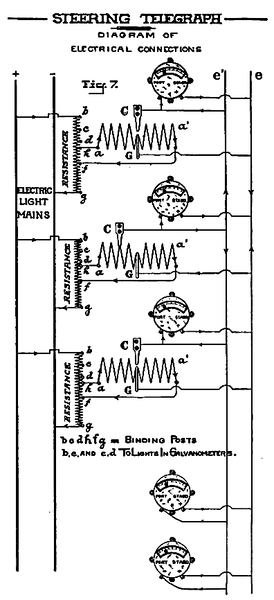 |
| Fig. 7 |
Fig. 7 is a diagram of electrical connections for a steering telegraph system, comprising three transmitters, shown on the upper part of the page, and two indicators shown on the lower part of the page.
The resistance wires, a a', are traversed by currents of electricity, furnished by any suitable source, such as a storage battery, primary battery, dynamotor, etc.; in Fig. 7 the source is the electric light mains of the ship, a suitable resistance being interposed, as shown, to reduce the current in each transmitter to about 2 amperes. The passage of a current of electricity through the resistance wire of any transmitter, such as the second transmitter shown in Fig. 7, is immediately due to a difference in electric pressure, or potential, between different parts of the wire; so that the permanent metallic con tact, G, and the traveling contact, C, are at different pressures or potentials. If the current is flowing in the direction represented by the arrow-heads, contact, C, is at a higher potential than G, so that a current of electricity will pass through any galvanometer connected to them, going in the direction from C to G, and move the galvanometer needle to the left. If, on the other hand, C were to the right of G, it would be at a lower potential and the current through a galvanometer connected to C and G would go in the direction from G to C and move the galvanometer needle to the right. If the contact, C, were at the middle part of the wire and rested on G, C and G would be at the same potential and the galvanometer needle would remain at rest in the middle of the scale.
In order that two or more transmitters may be connected independently, and yet be so adapted that any one transmitter may be used at any time, the contact, C, and the wire, G, are so arranged that the contact, C, does touch the wire when it is in its middle position. So long, therefore, as the contact, C, of any transmitter is in its middle position, that transmitter is not connected to a galvanometer and does not affect any galvanometer or any other of the transmitters. In the position shown in Fig. 7, the movements of contact, C, of the second transmitter affect the galvanometers just as though the first and third transmitters were absent. When not in use, the contact of each transmitter should be placed in its middle position, not touching the resistance wire. This caution is marked on each transmitter case. The amount of the movement of contact, C, may be shown on a graduated scale and the resistance in the circuit so adjusted and the galvanometers so marked that the galvanometer needles will point to the figure that indicates the movement of the contact, C. This method is like that adopted in the helm indicator, but a preferred method is that shown in Fig. 7, because the system is not affected by any changes of electro-motive force of the generator, and the work of adjusting the resistance is avoided. By the plan shown in Fig. 7, there is placed in front of each transmitter a galvanometer exactly similar to the galvanometers which act as indicators at the steering wheels. The operator, then, at any transmitter, moves his contact until the galvanometer in front of him points to the desired helm position-say, 20 degrees port; and the two indicators at the steering wheels will instantly show 20 degrees port.
A further advantage of the use of this galvanometer at the transmitter is that the operator always knows by its movements whether or not the apparatus is working.
In the absolute apparatus, as ordinarily constructed, the resistance wire, a a' is wound in a spiral groove on the circumference of a cylinder, D, of insulating material, such as rubber, as indicated in Fig. 8. The two ends of the wire are connected to flat springs, a a', against which press the ends of the binding posts, A, B. The permanent contact, G, is connected by a short pin to a metallic ring, R, placed at one end of the cylinder; and a flat spring, P, connected to the binding post, E, continuously presses on the ring, R. At the point where the permanent contact, G, is connected to the wire, the groove in the cylinder is cut down deep into the cylinder, so that the contact, C, cannot touch it. To accomplish this, in constructing the apparatus, the cylinder, D, is cut in half transversely, and the contact, G, after being soldered to the wire which is to be wound on the cylinder, is secured in position. Then the two halves of the cylinder are screwed together and the wire is wound in the groove. To produce movement of the contact, C, it is mounted on the nut, N, which travels on the screw, S, C being insulated from N. The pitch of the screw, S, and of the spiral thread in the cylinder, D, are the same, so that, as S is revolved by turning the handle, H (thereby turning D by means of the gear wheels shown), the nut, N, is moved along the screw, S, and the contact, C, along the wire, a a', the contact always remaining in the groove that holds the wire. The copper wires connecting the instruments should not be less in size than No. 16 American gauge.
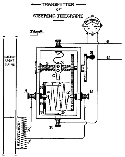 |
| Fig. 8 |
The transmitters of the steering telegraph are so arranged that any transmitter can be used independently of any of the others and produce the corresponding deflections in all the galvanometers, both of the transmitters and receivers, so long as both of the other transmitters are secured carefully at zero; but any movement of any transmitter while another is in use is indicated immediately by the erratic movements of all the galvanometers. In order to show clearly when a transmitter is at zero, a glass is placed in its face through which the sliding contact can be seen. When the transmitter is at zero the reference mark on the sliding contact is directly in line with the zero mark in the transmitter; and it can be secured in this position by means of a pawl which falls into a slot cut in the handle, H, Fig. 8.
The steering telegraph was given a year's test in sea service on board the U. S. S. New York, and the test having passed successfully, the apparatus has since been installed in the U. S. battleships Indiana and Massachusetts, using in each ship three transmitters and two indicators. It is now being installed in the Texas, and is to be installed in the Brooklyn.
Weight of indicator, 22 pounds.
Resistance of indicator, 60 ohms.
Weight of transmitter box, 6 pounds.
Diameter of indicator, 10 inches.
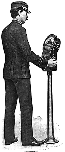 |
| Fig. 8a Electric Steering Telegraph. |
