[Trade Journal]
Publication: The Electrical Engineer
New York, NY, United States
vol. 22, no. 437, p. 267-269, col. 1-2
THE ELECTRICALLY DRIVEN MILLS OF THE PELZER MANUFACTURING CO., PELZER, N. C.
THE advantages incident to the driving of textile mills by electricity instead of by belt or rope drive from a steam engine are perhaps nowhere more emphatically demonstrated than in the great cotton mills of the Pelzer Manufacturing Company, at Pelzer, N. C. This company, organized in 1860, had gradually increased its manufacturing facilities until in the spring of 1894 it had not less than 53,500 spindles in operating in the three mills which it had located on the Saluda River. The entire power of the river at that point it then utilized to drive two of the mills. Mill No. 3 was driven by a belt from a 400 horse-power engine of Corliss type.
| |||
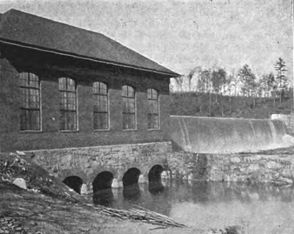
| Fig. 1 -- Power House and Dam, Pelzer Cotton Mill Plant. |
The Pelzer Company owned a large tract of land immediately adjoining the mills, and upon this it had erected besides the three mills just mentioned, three churches, schools, and the factory village, the whole property being controlled and supervised by the president, Capt. E. A. Smythe. The village is located about three- quarters of a mile from the Columbia and Greenville branch of the Southern Railroad, and a spur track is run from the line to the village. The corporation controls the Saluda River for several miles on each side of the Pelzer village, and in this distance owns a number of undeveloped water powers, in addition to those it had already utilized. The growth of the business of the Pelzer Company rendered an increase in the manufacturing plant necessary, and in 1894 plans were drawn for a new 55,000 spindle mill. The question of driving the mill, and consequently, its location, became the most serious it had to consider. A magnificent undeveloped water power existed not three miles down the stream from the present village, but if the new mill were to be erected by the side of this water power, it would be necessary to duplicate the mill village, etc., and would entail the cost of additional supervision, the distance between the two villages being too great to bring the new mills under direct supervision of the mills 1, 2 and 3. The formation of the land adjacent to the water power was also unfavorable to the erection of a mill at that point, unless at great expense. It would have been necessary to lay very heavy stone foundations under the entire building, which had been planned for 505 feet in length and 128 feet wide, as well as to extend the railroad track from the old to the new village. Before the magnitude of such a project even such enterprising mill owners as the Pelzer Company recoiled. A little before this time the owners of large cotton mills at Columbia, S. C., had decided to use electricity to drive their machinery. Their plant was already in operation and giving satisfaction, and the Pelzer Company, after an exhaustive examination, made a contract with the General Electric Company, in October, 1894, for an entire electrical three-phase generating and insulation motor equipment for the new mill, and a synchronous motor equipment for mill No. 3.
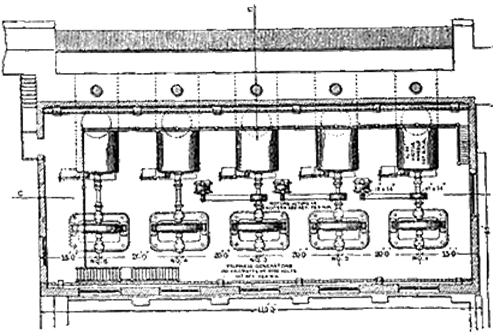 |
| Fig. 2 -- Plan of Pelzer Power House. |
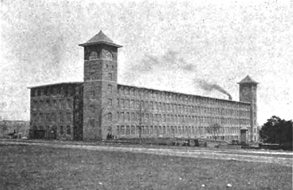
The plans were altered accordingly to comprehend a power house only at the site of the water power, and the erection of mill No. 4 itself in the vicinity of mills 1, 2 and 3. The new mill is 505 feet long by 128 feet wide, four stories high and contains 55,027 spindles. To obtain the necessary fall with a sufficient storage of water, a dam of solid masonry 32 feet high and about 450 feet long was thrown across the Saluda River, a spillway 300 feet long being provided in view of occasional heavy spring freshets. The available power is set down at 5,500 horse-power. The power house is of red brick, laid on masonry foundations, the walls being waterproofed for three feet above the top of the stone. The dam and power house were constructed by William Chapman & Company, Providence, R. I., and the water wheel plant by the Stilwell-Bierce and Smith-Vaile Company, of Dayton, O. Wheel pits and feeders are provided for five pairs of 29-inch horizontal Victor wheels, each of which, under the available head, will develop 1,000 horse-power. Three pairs of wheels only have been installed, but the other two will be put in as soon as the increase in the demand for power warrants the extension.
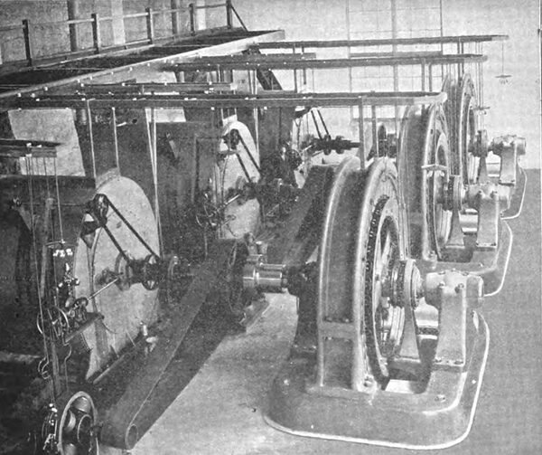
Each pair of turbines is connected to the armature shaft of a 1,000 kilowatt three- phase generator, delivering current at 3,300 volts when turning at a speed of 167 revolutions per minute. The exciters are multipolar dynamos of the General Electric slow speed type, and are directly driven by belts from the turbine shafts. The switchboard of the skeleton type located in the gallery, carries the special high tension switches the synchronizers and usual rheostats and measuring instruments, the busbars receiving the current direct from the generators without transformation. The high tension wires rise from the board to a small monitor on the dam side of the power house and pass out through this to the special glass insulators on the poles. These carry four cross arms. The top one carries two wires acting as lightning conductors grounded at every third pole; the second, third and fourth cross arms carry the generator circuits, while on the lowermost are strung the pressure and telephone wires. The total length of the pole line is 2-5/8 miles. Three-quarters of a mile from mill No. 4 the wires for the synchronous motor in mill No. 3 branch off from the main line.
| |||
| Fig. 3 -- Generating Plant, Pelzer Cotton Mill Power Transmission. |
A small tower erected immediately in front of the new mill receives the high tension wires which are carried down the interior and proceed into the basement of the mill by an underground tunnel. In the tower are contained the lightning arresters. The transformer room adjoining the repair shop in the basement receives the wires through porcelain lined holes in the wall, on a skeleton board carrying the necessary switches. The transformers are nine in number, three of which have a capacity of 265 kilowatts, and six of 275 kilowatt capacity. They are of the G. E. air blast type, in which the principle employed to keep them cool is to send a constant current of air through the laminations by means of two electric blowers. In the transformers the pressure is reduced to 200 volts, at which pressure the current is brought to the motors. There are also two transformers reducing the current to 114 volts for the 1,200 incandescent lamps used to light the establishment.
| |||
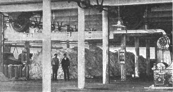
| Fig. 4 -- New No. 4 Pelzer Mill Operated Electrically. |
The motor equipment of the new mill aggregates 2,080 horse-power, divided into twenty- four motors, all of the G. E. induction type and located throughout the building as follows: Two of 50 horse-power each in the basement to drive the 75 horse-power each in the picker room on the first floor. These are directly connected to the shafting in the same manner as at the Columbia, S. C., mills, and run at 600 revolutions per minute. Four of 110 horse-power each, driving 720 looms on the first floor and 680 on the second floor, as well as five slashers. Three of 110 horse-power each, driving the carding machines of the third floor. Eight of 110 horse-power each, driving the machinery in the spinning room on the fourth floor. One of 20 horse-power operates the spoolers in this room and four of 5 horse-power supply power for the operation of the pumps. All of the above motors are non-synchronous, and are of the inverted type. They are suspended from the ceilings of the rooms in which they are employed. They have neither brushes, collector rings nor commutators, and consequently there is no sparking. The principal advantage presented by these motors is that they necessitate no attention whatsoever beyond that given to the bearings, and so long as these are kept properly lubricated, the motor will satisfactorily perform its duty. They are self oiling and are provided with oil glasses, by which the attendant can readily determine the amount of oil in the oil chamber. By fastening these motors to the ceiling a great saving in floor space is effected, and they are there beyond interference from curiosity, carelessness or accident.
| |||
| Fig. 5 -- Picker Room, Pelzer Mill, With Ceiling Motor. |
To drive the machinery, each motor is, as far as possible, connected by four belts, two overhanging pulleys being keyed to each end of the motor shaft. From each end the two belts lead in opposite directions to the shafting driven by the motor. This method of driving reduces to a minimum the amount of friction, while equalizing the strain upon the bearings and shaft. In cases where two belts only are driven by a single motor the pulleys are placed on one end of the motor shaft only, and the belts are led in opposite directions to the machinery shafting.
| |||
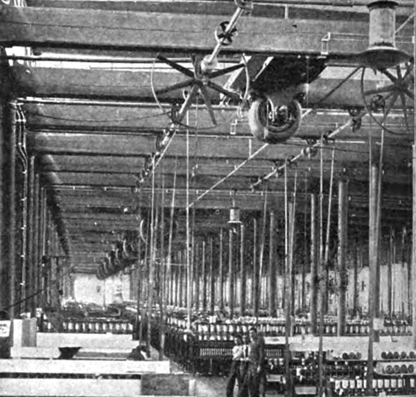
| Fig. 6 -- Spinning Room, Pelzer Cotton Mill, Motors on Ceiling. |
A glance at the economy induced by the adoption of electricity shows that the erection of this plant cost very little more than it would have done had the mill been located at the dam, on account of the expensive stone foundations which would have been required, the duplication of the mill village and the extension of the railroad. The mill instead of being located on low lying land near a river, is on a high, dry tract, where it receives the best light and ventilation. A consider able saving was effected in both shafting and belting. The widest belt in this mill using 2,200 horse-power is only 8 inches wide the largest shaft 2-15-16 inches in diameter. The saving in first cost of shafting and belting compared with that in a mill of identical proportions driven by mechanical methods, can be set down at about $10,000 . The omission of the belt tower, and its accompaniments, resulted in economizing a sum between $3,000 and $5,000. In mill No. 3, substitution of the 400 horse- power synchronous motor for the steam engine will do away with an annual expenditure for fuel of $10,000. The steam required for heating and slashing in this mill is supplied from the boilers in Nos. 1 and 2 mills, and thus the entire cost of fuel used in No. 3 mill will be saved by the substitution of the synchronous motor. This saving would more than equal the entire operating expenses, including interest on the electric plant driving both No. 3 and No. 4 mills, and lighting the latter. In other words, the cost of power for these two mills and the cost of lighting one of them would be no more than if the steam engine had been retained in No. 3, and No. 4 had been erected near the water power to be driven therefrom mechanically. All of the advantages of concentration, subdivision of power, more favorable transportation facilities, better light, and better ventilation are obtained without adding anything to the cost of manufacturing the output. On the other hand, it is obvious that they must result in a very material reduction in its cost.
