[Trade Journal]
Publication: The Electrical Engineer
New York, NY, United States
vol. 22, no. 431, p. 121-122, col. 1-2,1
ELECTRICAL TRANSPORTATION.
THIRD RAIL CONDUCTORS.
BY LEO DAFT.
THE account in the ELECTRICAL ENGINEER of July 1, of the excellent performance of the cars on the Nantasket Beach Electric road, recently equipped with a third rial, so vividly recalls the use of similar conducting devices in early electric railroad days, that I venture to relate a few experiences with third rails as conductors, in the hope that they may not prove entirely uninteresting at the present time.
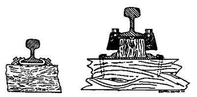 |
| Figs, 1 and 2. Daft Third-Rail Insulators. |
In October, 1883, I equipped 1.25 miles of the main line of the Saratoga, Mount McGregor and Lake George steam railroad, for experimental purposes, with a 35-pound third rail, placed midway between the service rails of the track, and insulated by means of wood blocks which had been thoroughly baked and plunged into boiling pitch while hot from the baking. The foot of the rail was further protected by sheets of soft rubber curled back over the flange and held by square washers under the head of lags screwed to the block beneath, Fig. 1.
The joints were first prepared by thoroughly cleaning the plates and points of contact underneath, when thin sheets of tinned copper were interposed and the joint firmly made up. This did very well for the middle rail, but the service rails were in such bad condition that we found it necessary to adopt some other method, and I finally decided to drill the foot of each rail on one side of the track and run a continuous copper wire with a turn under the heads of special clamp bolts in the newly-tapped holes. From this ground wire and bond combined a few cross bonds were led to the other service and clamped under freshly cleaned joint plates. It only remained to get the deep rust off the third rail, which was done by hanging a heavy board to the motor so that one end would trail on the track, and after attaching a segment of coarse emery wheel to the under side it was duly weighted and towed back and forth until the desired result was attained. The "weight" at first consisted of a 100-pound man, but I regret to add that after a few trips at dead of night our friend failed to find the novelty of the situation a sufficient inducement to continue the exercise, and a resort to inanimate material became imperative. The "collector" consisted of two bronze wheels, mounted on an iron frame in the form of an X, and capable of independent contact with the rail.
The motor ran over the section so prepared nearly every night for two or three weeks with a pressure of 100 to 130 volts, and, contrary to general expectation, the insulation was not low enough at any time to permit of lighting a 75-volt incandescent lamp, In circuit to third rail with line open, except once, when a 10-inch snowstorm was followed by a quick thaw. This rough test of insulation was applied because the use of galvanometer and bridge was difficult on account of strong local disturbances, and the halcyon days of high resistance Weston voltmeters were yet in the dim future.
I think the next use of the third rail in this country was on the Baltimore and Hampden electric road, which was a trifle over two miles long, in 1885. As this was an example of commercial use, having been ordered and promptly paid for in the ordinary course of business, continuing in daily use for four years, practically on the original lines, it may perhaps be deemed worthy of passing notice. In the spring of 1885 we began placing the 25-pound rail midway between the outer rails of the track, which was situated at the side of the road clear of the ordinary traffic for the greater part of the distance, thus affording a good opportunity for the use of surface conductors; and as the railroad company had some rail in stock they were naturally anxious to use that rather than buy other material which would not be available for renewal, in case of the absolute failure, which nearly all our good friends, and especially one eminent professor of physics, confidently predicted. This latter consideration prevented the use of a special section, which I had previously designed and submitted to the railroad directors, and which bore a very close resemblance to the rail recently laid at Nantasket; in all essential particulars one may say they are identical.
Figs 3, 4 and 5 are exact copies of the original drawing, made by our draughtsman from my sketch, and dated by him Feb. 10, 1885. The specification called for insulation consisting of hard rubber or fibre for Fig. 3, and wood, prepared by baking and boiling in pitch, for Figs. 4 and 5. Fig. 3 was also designed for the Baltimore road, but Fig. 2 was adopted as being cheaper and involving less delay. The turned blocks of wood were subjected to the above described treatment, and were then driven into the dovetailed slot of the iron shoe.
The rail head was completely incrusted with scale and rust, so that some means of cleaning was necessary, and after a dismal failure to reach the desired end with a gang of men armed with new files, I rigged up a coarse emery wheel in a frame attached to free out-board journals on the armature shaft of a small motor, and ran it by belt from the motor. The emery wheel was thus free to describe a circle, of which the frame and belts were radii, without changing the tension of the belt, and when placed on the front platform of one of the motors, with the emery wheel resting on the center rail and both supplied with current from the track, we found little difficulty in dressing the entire two miles in a few hours so as to afford almost perfect contact. Some fruitless efforts to make good joints by other means were quickly followed by substantial bonding with tinned copper bonds rivetted into the feet of the rails. So laid, the center rail continued in uninterrupted use until the autumn of 1889, and during that four years two, and sometimes three motors, always with trailers in tow, made daily runs averaging 75 miles each.
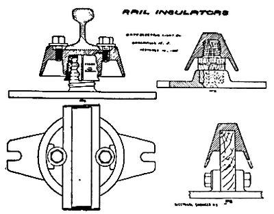 |
| Figs, 3, 4 and 5. Daft Third-Rail Insulators. |
It has been stated in one or two well-known books that the third rail on this road was abandoned in favor of an overhead conductor, but the latter was used only at crossings and through the village of Woodberry, in consequence of the frequent complaints of fastidious people who did not like to have their horses knocked down. The rail was protected throughout by a rough wooden guard, but the ingenuity of horses in getting down to it, despite the narrow slot, was past belief.
The potential used was 250 volts, from two compound machines in series. A few preliminary experiments with one of these machines, before the other arrived, occasioned the statement that only 125 volts was used, but save for a week or so, during the cleaning of the rail and other minor operations, the former pressure was employed from beginning to end.
That the insulation was imperfect, goes without saying, but it may perhaps be worthy of note that at no time was it low enough to appreciably increase the load, though occasions were by no means wanting when the hoods of several insulators were actually submerged during the sudden and violent storms peculiar to that region.
With a hooded rail and suitable wood blocks saturated with creosote by vacuum boiling, there was certainly no occasion to doubt the entire success of the Nantasket test, nor will there be serious trouble on sections of moderate length so insulated, unless much higher pressures than 500 volts be used or melting snow allowed to accumulate for considerable distances.
It now needs no prophet to read "the writing on the wall."
