[Trade Journal]
Publication: The Electrical Engineer
New York, NY, United States
vol. 19, no. 373, p. 583-591, col. 1-2
THE WORK THAT HAS BEEN DONE AT NIAGARA.
I.
No one contemplating the scene of the falling waters at Niagara can fail to be inspired with the sense of power there concentrated, and even the savage, ignorant of all applications of motive power, as he gazed upon the scene before the white man set foot within it, must have been imbued with a sense of the great force in constant action before him. Civilized man, however, has always cast wistful glances at the available natural powers of the world and hence it is not strange that Niagara has long been the goal for which enterprising enthusiasts have been striving. For years past, indeed, the power of the Falls has been utilized to a very limited extent in a few mills and factories scattered for a short distance on the brow of the gorge below the Falls, but it was not until the great success achieved by the electric methods of power transmission had made its impression upon the world, that capitalists could be induced to venture on the utilization of Niagara's power to an extent commensurate with the force available. Alluring, and promising as the project now appears after five years of work have been expended upon it, the beginning of this great enterprise was in one sense as difficult a task as its practical carrying out; and the trials and disappointments of its projectors recall forcibly the remark of Lord Brassey that the work of building a tunnel from England to China would be less arduous than the raising of the capital with which to carry it out. The credit of the pioneer work on the new Niagara utilization scheme rests largely with Mr. William B. Rankine, secretary of the Cataract Construction Co., whose persistence finally gained the recognition of Mr. Francis Lynde Stetson, the well known lawyer, of New York, and who eventually succeeded in interesting in the cause a number of well known and enterprising capitalists at the head of whom stands Mr. Edward D. Adams, a gentleman whose ability as a conservative financier has been recognized on two continents.
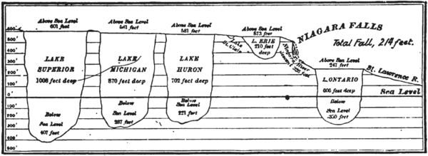 |
| Profile Showing Difference in Lake Levels of the Great Lakes. |
II.
Before entering upon the actual work already accomplished at Niagara it may not be uninteresting to refer briefly to the origin of the great source of power which the Niagara Falls Power Co. has spent so many millions in developing, in order that some estimate may be formed of the solidity and stability of the enterprise. One of the objections to the utilization of most water powers is their inconstancy, due to lack of water supply at different seasons of the year,an inconvenience, which has indeed resulted in a large reduction of the value of numerous waterpowers. That no such contingency need be apprehended at Niagara will become evident when we consider that the Falls constitute the spillway for a system of connected reservoirs consisting of Lakes Superior, Michigan, Huron and Erie, covering an area of over 90,000 square miles and draining a watershed area of nearly 250,000 square miles, extending half across the continent. The relation of the lakes to the Falls is well shown in the profile on page 583 which also gives the fall of level from lake to lake.
| |||
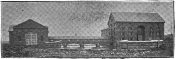
| Main Power House and Transformer House. |
| |||
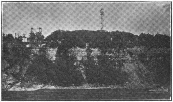
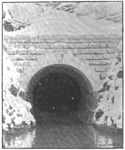
| Niagara Gorge, Showing Portal of the Great Water Power Tunnel. |
| |||
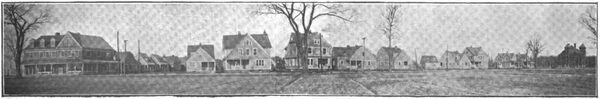
| View of Echota, the Residence Section, Adjoining the Factory Sites of the Niagara Falls Power Co. |
| |||
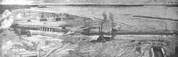
| Bird's Eye View Showing Preliminary Work on the Power Canal. |
The volume of water which passes over the Falls has been variously estimated, the most reliable figure putting it at 205,000 cubic feet per second, corresponding to 7,000,000 n. r. actually available at the turbine shafts if the total height of the Fall from the Upper Rapids to the Whirlpool Rapids were redeemable.
But as the Power Co.'s tunnel provides for a fall of only 140 feet the power available if the entire Fall were utilized would be about one-half the above figure, or 3,500,000 H. P. As the plans of the company embody the initial diversion of water equivalent to only 100,000 H. P. on the American side, and 250,000 H. P. on the Canadian, the diminution of the level at the brink of the Falls will be barely perceptible. In fact, nobody but trained observers familiar with the scene could notice it.
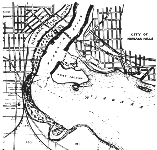 |
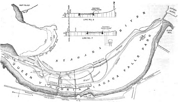
| Map Showing Location of Power Houses on American and Canadian Sides. |
The Niagara Falls Power Co. received its charter in 1886, but it was not until four years later that the actual work of construction was begun. In the mean time the studying of the methods for carrying out the engineering problems involved had been entrusted to the International Niagara Commission, consisting of Lord Kelvin, Colonel Turettini, Prof. Unwin, Dr. Coleman Sellers, and Prof. Mascart, who invited the leading electrical and engineering specialists of the world to submit plans, and these were finally passed on by a board consisting of Dr. Coleman Sellers, Mr. Clemens Herschel, Major G. B. Burbank and Mr. John Bogart, with Prof. George Forbes as consulting electrical engineer.
III.
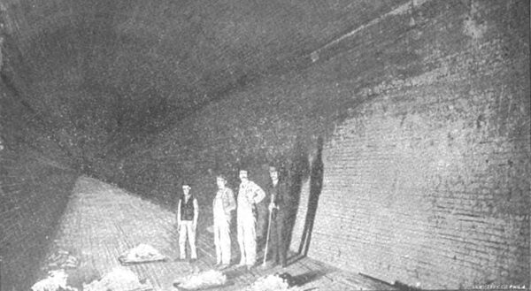
The plan finally adopted embraced the construction of a canal about miles above the American Fall, tapping the river, with a width of 300 feet and 1,500 feet long, and having a depth of 12 feet. Wheel pits sunk along the edge of this canal lead the water to turbines at the bottom, and the discharge is carried off through a great tunnel 19 feet wide by 21 feet high, 6,700 feet long, passing under the town of Niagara Falls and emptying into the chasm just below the Suspension Bridge, as shown in the view on page 583.
IV.
Electricity having been adopted as the system of distribution and the Tesla two-phase having been selected as that best adapted to fulfill the requirements which a diversified number of manufactures and utilizations might call for, the type and arrangement of generators and their connection to the turbines was given especial attention.
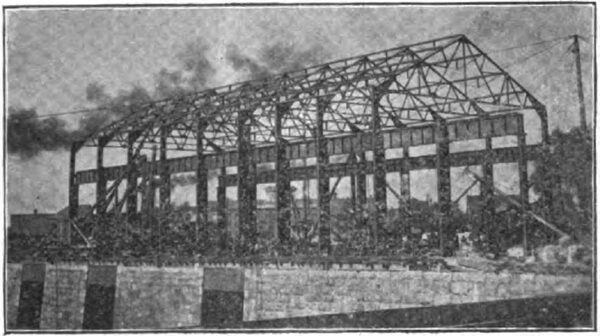
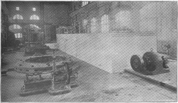
After much deliberation it was decided to erect 5,000 H. P. units, and some of these have now been installed in the power house, views of which are given on pages 585 and 586. This station is designed for an ultimate capacity of 50,000 H. P., but for the immediate present only three units of 5,000 H. P. each will be set up.
| |||
| Steel Skeleton of Power House. |
| |||
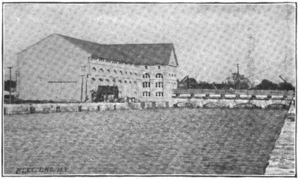
| View of Niagara Power House From Canal. |
| |||
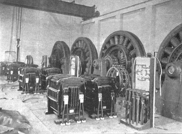
| View in the Power House, Showing Generator With Armature Exposed, and the Switchboard Gallery. |
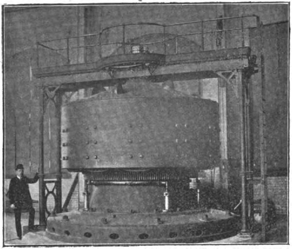
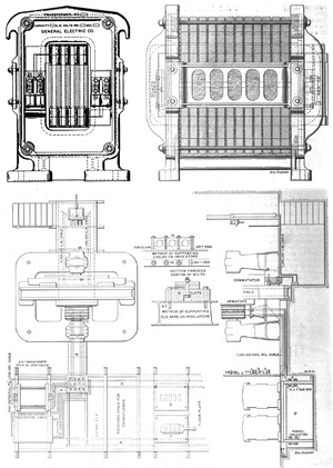
The illustration on this page shows one of the Tesla two-phase generators now erected in the power house, and a good idea of its construction can be obtained from the sectional view on the page 586. To a circular foundation is bolted a vertical cast iron cylinder, provided with a flange on which the stationary armature rests. The inner part of the cylinder is bored to the shape of an inverted cone and serves as a bearing for another conical piece of cast iron, supporting the shaft?bearings. The armature core is made of thin, oxidized iron plates, held together by 8 nickel-steel bolts. In the outer edge of the plates are 187 rectangular holes to receive the armature winding.
The outer rotating field magnet consists of a wrought steel ring to which are bolted the 12, inwardly projecting, massive cast iron pole pieces. The ring constituting the field magnet is supported by a six-armed cast-steel spider keyed to a vertical axis. The field-magnets act also as a flywheel. The shaft rests on two bearings supported by four arms projecting from the inner adjustable cast-iron cylinder. The bushings of the bearings are made of bronze provided with zigzag grooves in which oil constantly circulates. On the outer side of the bushing there are also grooves into which cold water may be pumped, if required.
| |||
| 5,000 H. P. Two-Phase Generator in Power House. |
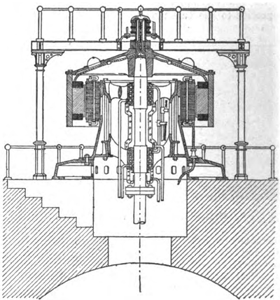 |
| Niagara 5,000 H. P. Two-Phase Generator Section. |
The armature conductors are rectangular copper bars, 1 ¼ x 1 5/16 of an inch. Each of the 187 holes of the armature contains two of these bars, surrounded with mica. The upper and under sides of the armature are connected by means of V-shaped copper bars, riveted to the ends of the bars which project out behind the ends of the armature.
The connections are made so as to give two independent circuits. A pair of cables connects each circuit with the switchboard. The magnet-winding also is composed of bent copper bars, air-insulated, inclosed in brass boxes, two of which are fastened to each pole-piece. Continuous current for exciting the field magnets is obtained from a rotary transformer.
| |||
| View in the Great Tunnel. |
| |||
| View of Its Portal Below the Falls. |
The current is conducted to the field coils by means of a pair of brushes and two copper rings fixed to the top of the shaft of the generator. At a speed of 250 revolutions per minute the machine produces two alternating currents, differing in phase of 90 degs. from each other, each of 775 amperes and 2,250 volts pressure. The alternations are 50 per second. The height from base of bed plate to top of machine is nearly 13 1/2 feet. All the generators were built by the Westinghouse Co.
V.
The general plan of the connection of generator to turbines situated 150 feet below is shown on page 587 and the illustration on page 587 gives a section of the turbines, which were designed by Messrs. Faeseh & Piccard, of Geneva, Switzerland, and built by the I. P. Morris Co., of Philadelphia. They are of the Fourneyron or Boyden type and special methods were adopted to relieve the bearings of the pressure of the superincumbent mass. The weight of the vertical shaft and the attached portions of the dynamo, amounting to about 152,000 pounds, is taken care of by closing the bottom of the casing so that the water cannot act downward upon any of the parts attached to the shaft, while in the upper end of the casing are apertures through which the water can act upon the under side of the disc carrying the movable blades of the upper turbine and relieve the bearings of the weight of the shaft. In this way the weight of the water column is sustained by the stationary portions, and the pressure due to the head made to act upward for supporting the weight of the revolving shaft, which is thus nearly in the condition of a shaft spinning upon the water. The area involved is so proportioned that when the wheels are lightly loaded the upward pressure will be some 2,000 pounds in excess of the weight of the shaft, and when the wheels are running at full gate about the same amount less than the weight of the shaft., on account of the lesser pressure in the casing. This variation in pressure and direction is taken care of by a thrust bearing shown in section in the illustration. The shaft consists of a steel shell about a foot in diameter, with smaller solid portions for the journals.
| |||
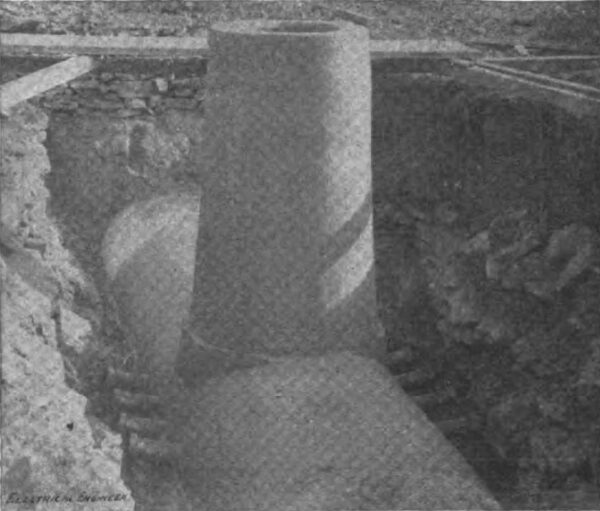
| Conduit for Electrical Conductors Showing Manhole and Branch Outlets. |
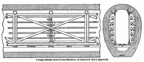 |
| Longitudinal and Cross Section of Electric Wire Conduits. |
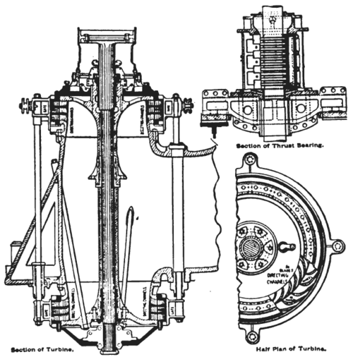 |
| Niagara 5,000 H. P. Turbines. Vertical and Horizontal Sections. |
|
| Section of Turbine Shaft, Showing Power House and Tunnel. |
VI.
In carrying out its project of power utilization the Niagara Falls Power Co., has left the power user entire freedom in the selection of his methods. Thus he can dig his own wheelpits and put in his own turbines at $9 per H. P. per annum, or he can take the power from turbines furnished by the company at $12 to $15, or again he can obtain his power through motors fed by the current generated at the power house, at from $20 to $25 per H. P. per annum. For the latter purpose the lands of the company which include 7500 acres of factory sites and dwelling lots, have been provided with large conduits for carrying the electrical conductors, the general arrangement of which is shown on this page. The conduits are 5 feet 6 inches high by 3 feet 10 inches wide inside, and are built with 12 inches of Portland cement and gravel, and backed up by about one foot of masonary [sic] masonry at the bottom and extending up the sides about 3 feet. The conductors are carried on insulated brackets on both sides. A track extends throughout the length of the conduit, upon which an electrically propelled car will carry the linemen between wire screens that protect them from the conductors and allow every portion of the line, brightly illuminated by the passing car, to be thoroughly inspected with absolute safety. The brackets are placed 30 feet apart. The engraving on this page shows one of the manholes which are placed at intervals of 400 feet. At the bottom will be seen the small outlets for tapping the conductors in the conduits. Besides this provision for the local distribution of power, the Niagara Falls Power Co. has wisely made provision for the calls which must inevitably follow for Niagara's power from a distance. With the future in view, there has been constructed a transformer house directly opposite the main power house across the inlet canal and connected to it by a graceful stone bridge. This building will contain the step-up transformers for raising the potential from the 2,000 volts delivered by the generators to that required for high potential transmission. We need only remark here that rights of way for a pole line to Tonawanda, directly north of Buffalo, have already been secured so that it requires merely the sanction of the Buffalo City Council to bring the power into that city.
 |
| Plan and Section of Pittsburgh Reduction Co.'s Electric Plant at Niagara Falls, With Details. |
VII.
The low cost of Niagara power has already attracted some large power consumers. Among these is the Niagara Falls Paper Co. who have contracted for 6,000 H. P. developed from their own turbines, at a cost of $9 per H. P. per annum. The first to employ electric power will be the Pittsburgh Reduction Co., who will start with 2,000 H. P. As the reduction of aluminum requires the use of the continuous current it became necessary to install a transforming plant. The illustration on this page shows the company's transformer room which is 87 feet long by 50 feet wide. At the present time there are installed four rotary and eight "static" transformers. The arrangement of these is shown in the plan on page 588. The "static " transformers, as they, are called to distinguish them from the rotary, have a capacity of 200 K. W. each and receive the 2,000 volt alternating current direct from the power house through conductors laid in the conduit described above, and transform it down to 115 volts at their secondaries. This 115 volt alternating current is then led to the rotary transformers and converted into direct current at 160 volts, the pressure required for aluminum reduction. The whole plant will have a working capacity of 7,000 amperes at 160 volts, with one set of machines in reserve. The static transformers are mounted in pairs over a pit, and will be ventilated by a low pressure air-blast introduced from below. The Carborundum Co., of Monongahela City, have also erected works close beside those of the Pittsburgh Reduction Co., and will start with 1,000 H. P.
| |||
| Interior of the Power House of the Pittsburgh Reduction Co. |
Having in view the growth of the population attracted by the works to be established on their property, the Niagara Falls Development Co. has reserved a considerable proportion of land for residence purposes and has already laid out streets and built a number of dwellings; a view of one of these streets is given at the foot of page 583. The sanitary works, such as water supply, sewerage system, etc., have been carefully looked to so that this new town called Robots will rank among the best equipped in the country from the sanitary standpoint.
 |
| Plan for One Power House and One Canal. |
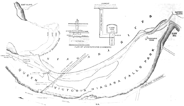 |
| Plan for Placing Dynamos in An Underground Chamber. |
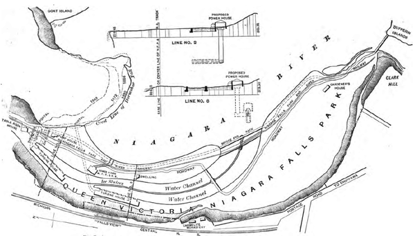 |
| Plan Adopted for Two Power Houses and Two Canals. |
VIII.
Thus far we have only considered the, work done on the American side of the Falls; but, as remarked above, plans are already complete for the utilization of the Falls on the Canadian side. This work will be carried out by a company closely affiliated with the Niagara Falls Power Co., and we give on page 591 the plan just accepted by the Canadian Government for carrying out the work. As will be seen, it contemplates the ultimate erection of two power houses, with a capacity of 125,000 H. P. each, and each fed by a separate canal. The water discharged by the turbines will be carried to the outlet through tunnels having lengths respectively 300 and 800 feet, so that the great cost involved by the long tunnel on the American side will be entirely avoided. Of the other plans submitted that on page 590 contemplated the erection of a single powerhouse-with one canal. The third plan submitted and shown on page 590 was evolved by Prof. Unwin and contemplated the excavating of a dynamo and turbine room directly under the Horse Shoe Falls and a short distance back of the brink, connected to the shore by a large tunnel. By boring a vertical shaft the water would be admitted directly to the turbines placed in the dynamo room underneath. The boldness of this plan detracts nothing from its merits.
With the American and Canadian power plant fully developed there will be available 350,000 H. P., a quantity which can best be realized by stating that the total power of the stationary engines in the whole State of New York barely exceeds 500,000 H. P.
The work undertaken by the Niagara Falls Power Co. in its early stages gave rise to doubts in the minds of many as to the ultimate success of the undertaking from a financial standpoint; but no one who has given the matter close study, and having before him the evidence of the work already accomplished will now seriously venture to predict a failure; on the contrary as each new field for the utilization of the power opens up, the foresight of the promoters of the enterprise comes home with redoubled force, and enhances the credit due them as the originators of the greatest power engineering work the world has ever seen.
