[Trade Journal]
Publication: Electrical World
New York, NY, United States
vol. 30, no. 14, p. 379-382, col. 1-2
The Lachine Rapids-Montreal Electric Power Transmission System.
LACHINE Rapids, in a certain sense, made Montreal. The St. Lawrence, navigable for boo miles from the sea for large vessels, here descends a chain of turbulent rapids, and here Jacques Cartier halted in his attempt at a westward passage to China. Three hundred and sixty-two years later the rapids, which mark the head of navigation and determined the position of Montreal, are harnessed for the service of the city which has grown op below them. The scheme of obtaining power from these rapids is by no means a new one, having been proposed and forgotten a dozen times within the century. It was not until the perfection of electrical transmission methods. however, that work was seriously begun.
| |||
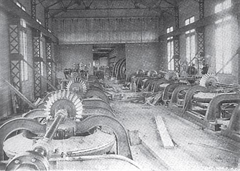
| Interior of One of the Gearing Rooms, Showing Governors. |
In 1895 the Lachine Rapids Hydraulic & Land Company commenced the construction of the great water-power-development works at the rapids, and, after exploiting a project for the direct utilization of the power at the wheels, decided to transform the whole output of their plant into electricity, and transmit it to Montreal, or elsewhere, as might be profitable. The engineering work done under the auspices of this corporation is bold to a degree, being in some respects without precedent, and both its financial and engineering promoters are worthy of the greatest credit for their persistence in the face of many natural obstacles and much adverse criticism.
| |||
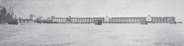
| A Winter View of the Uncompleted Power House From the Forebay. |
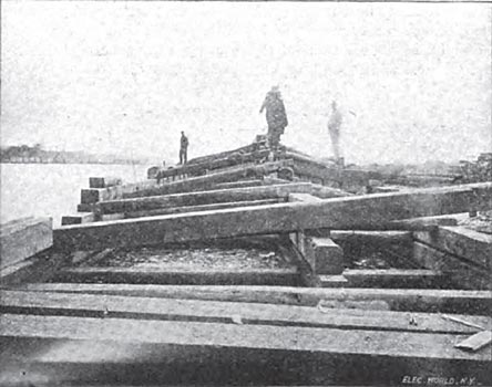
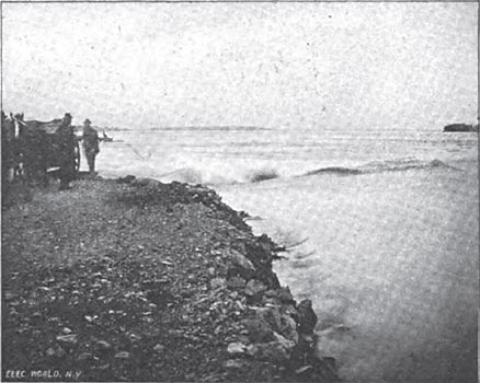
The Lachine rapids are divided into two channels by an island, the Isle au Heron, and the smaller division, on the left, or Montreal side of the St. Lawrence, was chosen for the scene of the power development. Here, in the current of nearly 15 feet per second a dam, parallel to the shore and about a mile long, was constructed, and the channel thus formed blasted out and deepened. The dam is, for the most part, built of 12x12-inch timbers, filled with boulders. Its facing is of two thicknesses of 3-inch plank, with broken joints, and in general cross section it is square. The crest is sloping and is topped with heavy hemlock logs, squared on three sides, the fourth side, with the natural curvature of the tree, being uppermost. At the upper end of the channel, between the dam and the shore, which is about moo feet wide, a number of heavy piers support a boom to deflect floating ice into the main current of the rapids. The wing dam ends in a granite pier adapted for ice breaking, and built of heavy stones, solidly keyed together by a peculiar construction.
| |||
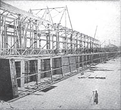
| Looking Down the Power House From the Centre. |
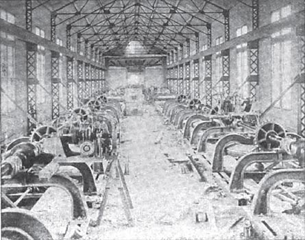
At a point about 1200 feet from the lower end of this artificial canal a cross dam of dressed stone 1000 feet long serves to give the necessary difference in level, and to contain the whole of the hydraulic machinery. Upon this is built the power house, which is probably the largest structure of its kind. This building consists of three dynamo rooms and four rooms for the wheel gearing, the whole being 1000 feet in length, 61 feet wide at the dynamo rooms and 40 feet wide at the other portions. It is solidly built of steel beams, having brick walls in the dynamo portions and a corrugated iron exterior with a lining of heavy felt, and a ceiling of matched hoards in the other parts. The roof is celled inside throughout and slated for its whole length. The floor is of steel I beams and concrete covered with one-inch slate slats in the dynamo rooms, and heavy boarding in the connecting portions.
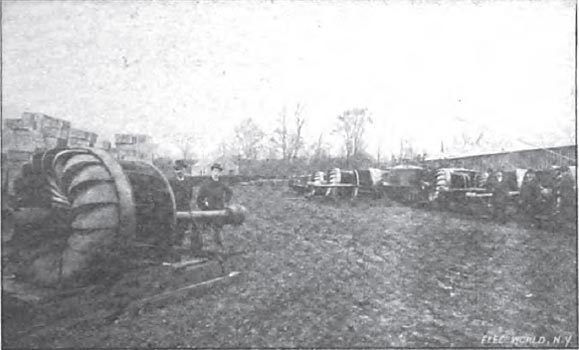
The seventy-two turbines are of the vertical shaft pattern, each 57 inches in diameter, and giving, at 83 r. p. m., with the normal head of 16 feet, 300 horse-power each. Six of these are attached by bevel gearing to each of the twelve horizontal dynamo shafts. The wheels are of a submerged type, having cylinder gates and no draft tubes. The massive bevel gearing consists of a steel pinion on the dynamo shaft and a crown gear on the wheel shaft, provided with maple teeth, the combination proving very effective and singularly quiet in operation. The most interesting feature of the hydraulic plant, however, is the governing mechanism, one governor controlling each gang of six wheels.
A sensitive ball governor is operated at a high speed by a belt from the main shaft. This controls a scale-beam lever, having at each end an electrical contact and steadied by a small alcohol dash pot. The electrical contacts control two powerful electromagnets adapted to move a pair of friction discs, keyed on the main shaft, to the right or left. These engage with other friction discs, to which are connected a powerful screw gearing which controls, through a system of levers, the cylinder gates of the six wheels. These gates are counter-weighted to decrease the effort necessary for their control. The governor will shut off all the water from full head in nine seconds, and under ordinary running conditions is almost as perfect in its control of the wheels as the best types of steam engine governors. These machines, as well as the wheels and gearing, were made and installed by the Stilwell-Bierce & Smith-Vaile Company, of Dayton, Ohio, to whom much of the credit for the successful performance of the plant belongs.
| |||
| One of the 750 Kw 4400-Volt Dynamos. |
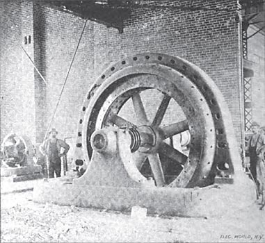
The dynamos are to be twelve in number, although only four are now in operation. These machines are of the revolving field type, and are rated at 750 kw each. They are wound for three-phase current at 4400 volts direct from the armature, and operate at a periodicity of 60 cycles per second at their normal speed of 175 r. p. m. An exciter is provided for each machine, consisting of a 40-kw four-pole generator, giving 150 volts at 875 r. p. m. These are belted from pulleys on the main shaft, and the four for each group of four dynamos are worked in parallel. These exciters also furnish current for the electrical governors previously mentioned. Both dynamos and exciters were built at Peterborough, Ont., by the Canadian General Electric Company.
The permanent switchboards, of which there will be three, one in each dynamo room, are not yet installed. They will be of a simple type. The temporary switchboard for two dynamos is of white marble and contains three single-pole, single-break, knife switches for each dynamo, one in each phase, mounted on high corrugated rubber bases. The exciters are compound wound and are connected through three-point switches. Thomson alternating voltmeters, 0 to 6000, and ammeters, 0 to 200, are in the main circuit, while the lamps used to illuminate the board are used as detectors in synchronizing the dynamos for parallel operation. The exciter circuit is provided with Weston volt and ampere meters. No circuit breakers are used, long fuses of the General Electric type, blowing in a magnetic field, being used in each phase. There is no other protection against lightning in the power house than that provided by these fuses.
| |||
| The Cross Dam and Power-House Framing. |
An interesting feature of the power house is the absence of all fire and chimneys. It is heated throughout by electric heaters, manufactured by the Canadian General Electric Company, and it is expected that, even in the climate of Montreal, they will prove sufficient. The flat heaters are arranged against the walls, about 30 inches from the floor. No data of their current consumption have as yet been given out.
| |||
| A Few of the Turbines. |
The circuits leave the building through appropriate ducts in the walls, and are connected just outside of the building to the bare wires of the pole line. These are dead-ended against the end walls of the building through about a dozen globe-pattern street-railway strain insulators.
The aerial line to the first sub-station is 30,000 feet long, the circuits being composed of 0 bare copper wire. This is sustained by porcelain insulators of the Niagara type, made by the Imperial Porcelain Works, of Trenton, N. J., mounted on locust pins. The circuits are run in triangles of 18 inches on each side. The poles are of iron, of a lattice construction, and are set 104 feet apart and 7 feet deep in concrete. Each is tested before use under a lateral strain of 6200 pounds, so that it may withstand the wind pressures of the severe winter storms of the Canadian climate. The line is protected at frequent intervals by Wirt lightning arresters of the Niagara pattern. The full load drop from dynamos to transformer secondaries will be to per cent.
| |||
| On the Wing Dam. |
| |||
| Building the Wing Dam. |
In the city of Montreal the company has three power sub-stations. In the plant of the Citizens Electric Light Company, owned by the Lachine Company, three static transformers, of 150 kilowatts each, reduce the line current to 2000 or 1000 volts, three-phase and two-phase. These transformers, like all the others employed by this company, were built by the Wagner Electric Manufacturing Company, of St. Louis. They are oil insulated and are cooled by water jackets. Every transformer is tested for one hour at 25,000 volts before being installed. From this sub-station there are already operated 20,000 incandescent lamps.
In another sub-station static transformers and a rotary converter of 200 kilowatts, built by the Walker Company, Cleveland, Ohio, will be installed to supply direct current at 250 volts to a district largely filled with motors adapted for this current.
The arc-lighting sub-station will contain two sets, each consisting of a synchronous motor of the type of the generators, being 200-kw capacity, direct coupled to two 125 light arc dynamos. The company is now operating 350 street arcs by steam, and these will be connected with this sub-station.
In addition to these sub-stations 8o miles of conduits have been laid, including one which carries the main line under the Lachine Canal. In these conduits the three-phase line current at the full pressure will be carried in three-wire cables, of which about 4 miles are already installed. Manholes at convenient intervals will contain static transformers, giving 52 or 104 volts in each phase for incandescent lighting, or such arrangements of phases and pressures as the motors of the immediate district may require. The paper-insulated cables and cement-lined tubes for the conduits were furnished by the National Conduit & Cable Company, of New York. The Lachine Company expects to construct an electric railway to a point near the power house, where it owns a large tract of land, very beautifully situated, in view of the rapids. Contrary to precedent, it is intended to develop this as a residence district, and not as a manufacturing site.
It is the intention of this company to sell current at one-half cent per ampere hour at 52 volts. Motor current is to be furnished at a correspondingly low rate, and a strong effort will be made for the general introduction of electric cooking and heating apparatus in Montreal and-its vicinity. It is claimed that this company can profitably compete for heating with anthracite coal at $6 per ton.
Great care was necessary to guard against the dreaded anchor ice, or frazil, the bane of water powers in high latitudes. As has been described, the upper end of the raceway at Lachine is guarded by a substantial boom, inclined to the direction of the current, which is intended to deflect floating ice. A system of other booms, in the still water of the basin above the power-house dam and within the wing dam, acts as further safeguards, but the greatest reliance is placed in the small velocity of the water in the intake, which will conduce to the early freezing of the surface. It is held by experts in the matter that frazil will not form under surface ice.
A more formidable difficulty, the blocking of the 1200-foot tail race by ice, has been met in the same way. An enormous amount of blasting, removing the hard limestone of the bed of the St. Lawrence, resulted in a mean depth of 6 feet for this tail race, and will so reduce the velocity of the water in it that it is confidently expected to freeze over the surface early in the season, leaving a free passage, clear of anchor ice, below.
On Saturday, September 25, the plant was formally opened, the mayor of Montreal turning on the water. Mrs. G. B. Burland, the wife of the president of the company, closed the Switch which turned on the Lachine current at Montreal, amidst much applause from the 2000 or more guests present.
This large enterprise is chiefly due to the efforts of Mr. W. McLea Walbank, the managing director of the company, and chief engineer of the construction. Messrs. T. Pringle & Son, of Montreal, were associated with Mr. Walbank as mechanical engineers. A curious feature of the enterprise, and one worthy of enthusiastic commendation, is that every dollar of the $1,400,000 required was paid in cash subscriptions, and that the whole construction was on a cash basis. The shareholders are nearly all residents of Montreal and Ottawa, and the enterprise is purely Canadian.
