[Trade Journal]
Publication: Electrical World
New York, NY, United States
vol. 30, no. 25, p. 723-725, col. 1-2
The Newcastle-Sacramento Transmission Plant.
ON the Sierra Nevada divide, northeast of Sacramento, Cal., the South Yuba Water Company owns and operates an enormous irrigating system, with nineteen storage basins, over 400 miles of canals, thirteen distributing reservoirs, and a network of canals, flumes, tunnels, pipe lines and lakes, covering two counties. At various points on the canal system are "drops," or sudden falls. The most important "drop" is one of 464 feet, of which 400 feet is utilized for the driving of the power plant of the Central California Electric Company, a corporation closely allied to the South Yuba Water Company.
| |||
| Local Lighting Plant in Generating Station. |
The water is carried from a reservoir to the power house, a distance of 6400 feet, in a 24-inch pipe of riveted sheet steel. The pipe is buried about 2 feet underground. Its thickness increases as it approaches the power house from No. 12 to No. 6 B, W. G. At the power house the pipe forks, in a heavy cast-iron Y, into two 15-inch pipes of No. 6 steel, running to the Ys on the Pelton water wheels. These wheels are a special design of the double pattern, two 48-inch wheels being direct coupled to each of the two 400-kw generators. The wheel buckets are of the Dodd pattern, with nozzles arranged to be deflected by means of hand levers located near the switchboard. No automatic water-wheel governors are used, the regulation being effected manually by the switchboard attendant. This does not require very close attention, as "the plant runs under a load so evenly laid on or taken off that every change can be anticipated, and even a waste of water avoided." The tail races are of substantial construction, and have heavy granite slabs at the bottoms. The power house foundations are about 6 feet deep, and of concrete and granite. The building itself is 80 feet by 30 feet, and its sides and roof are constructed of corrugated iron on a wooden framework. The Westinghouse Electric & Manufacturing Company supplied the entire electrical equipment of this plant, consisting of:
| |||
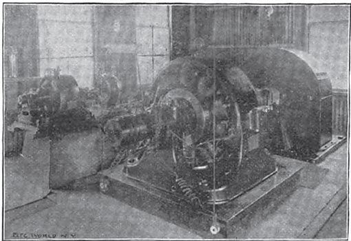
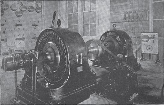
| Main Wheels, Generators and Exciters. |
Two A. C. two-phase generators.
Two exciters.
Generator switchboard.
Step-up transformers, two-phase 500 volts to three-phase 15,000 volts.
Twenty-eight mile three-phase 15,000-volt transmission line.
Fifteen thousand volt receiving switchboard.
Reducing transformers, three-phase 15,000 volts to two-phase 2000 volts.
Distribution switchboard.
Two-thousand volt circuits.
Transformers for motors and lights.
| |||
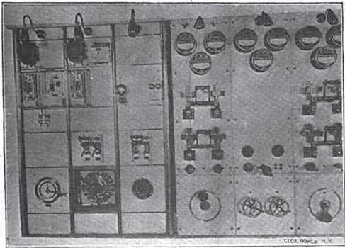
| The Main Switchboard. |
The two 400-kw generators arc of the inwardly projecting field and revolving armature type, and run at a speed of 400 r. p. m. They generate two-phase alternating current of 7200 alternations per minute, at 500 volts. The armature is not wound with wire, but with copper straps of the form and dimensions best suited to the armature slots. Each coil consists of a single turn of this copper strap, which is thoroughly insulated before it is placed in the armature grooves. After the coil is in position, strips of fibre are placed in each slot just over the bar and held in place by fitting into small grooves in the sides of the slots. Ventilation of the armature is effected by a number of radial openings between the laminations, from the open spider to the surface. The machines are excited by two 15-kw 125-volt exciters, driven by separate wheels, each exciter having ample capacity for exciting both of the generators.
The wires from the machines lead directly to the main switchboard, which consists of three panels, one for each generator and one for the exciters. Each generator panel is provided with two double-pole carbon-break main switches, an ammeter in each phase, a voltmeter on one phase, plug switches for the field circuit, and a rheostat. On one of the generator panels there are two lamps, which are used in synchronizing the machines. The middle panel contains the rheostats, switches, ammeters and voltmeters for the exciters.
At one end of the board on a swinging arm is a voltmeter, connected with a compensator mounted on the back of the board. This voltmeter indicates the pressure on one of the phases, and the compensator introduces a drop corresponding to that in the main transmission circuit, so that the instrument indicates the pressure at the sub-station in Sacramento. When there is a light load and a small drop the compensated voltmeter and the voltmeter on the generator panel will read practically the same, but when there is a full load the E. M. F. on the generator must be increased until the compensated voltmeter gives the proper indication. The difference between the indications of the voltmeter connected to the bus bars and that of the compensator obviously gives the drop in the line.
Each generator is connected directly through the switches on the switchboard and fuses to the primary of the step-up transformers, which arc connected to transform from two phase to three phase, and deliver current at 15,000 volts to the transmission line. Four step-up transformers, each of 150 kilowatts, are connected on the Scott system in two pairs of two transformers each for the two-phase three-phase transformation. The terminals from each set of transformers arc connected through fuses directly to the transmission line. Both step-up and step-down transformers are oil insulated. The coils of the transformers stand in vertical planes, and are spread apart to allow a free circulation of the oil between the coils, thus securing a high insulation and enabling the oil to come in close contact with various parts of the winding, and convey the heat to the case by convection. Ample provision is made for cooling by air circulation without the use of water jackets or fans, but by the simple provision of vertical air tubes through the walls of which the ln-at is transmitted from the oil to the air.
| |||
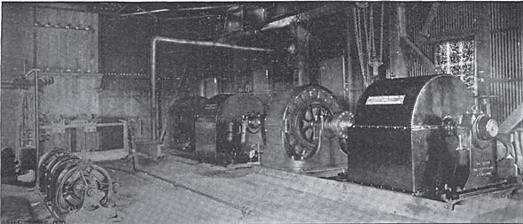
| Multiphase Motor Driving Arc Generator. |
The pole line is substantial and well constructed. For five miles redwood poles. 30 feet long, 10 inches square at the. butt, and 6 inches square at the top, are planted 5 feet in the ground. For the remaining 23 miles the poles are 40 feet long of Washington cedar and planted feet deep. The distance between the poles is 125 feet. The cross arms arc 5 feet long, with two pins and two insulators. One set of insulators is secured to the peaks of the poles, on iron Ys. There is a light arm also attached to the poles for telephone wires. The three wires of the main circuit are No 4 B. & S. bare copper, secured one to the insulators on the peaks of the poles and the others to those on the top cross arm.
The second cross arm carries the wires for local service in Placer County. The insulators are of the Locke pattern, triple petticoat, and made to carry a current of very high potential without cracking or puncturing. They are secured to the cross arms by steel pins, thus providing a solid support for the wires. General Manager Van Norden states that these insulators have proved very satisfactory for the transmission of 15.000 volts. The line worked perfectly when the plant was first put in operation, and only a few of the 6000 insulators have developed any weakness since they were put in service. Some of these appear to have been broken by malicious shooting or by other non-electrical causes. When these accidents occurred the poles were set on fire by the current, which, however, did not interrupt the service as the pole burned away, leaving the wires hanging free. On one occasion two poles nearly a mile apart were found to have been burned, owing to faulty insulation, which allowed the current to leak from one wire through one of the poles to the ground, and back through the other pole to another wire of the circuit. Both of these poles were badly burned, but neither the attendant at the generating station nor the attendant at the sub-station knew that anything unusual had happened.
Each end of the transmission line is protected by Wurts non-arcing metal lightning arresters. There arc six choke coils connected in series in each of the three wires. From the line at the junction with the coils there are spark gap paths to the ground, through which lightning discharges can pass. No resistances are introduced in the ground circuits, so the lightning discharge encounters nothing except the spark gaps on its way to the earth.
At the sub-station at Sacramento the current is received on a high tension switchboard panel, by which it may be delivered to either or both of two sets of step-down transformers. Fuses are inserted between the panel and the transformers.
| |||
| Step-Up Transformers. |
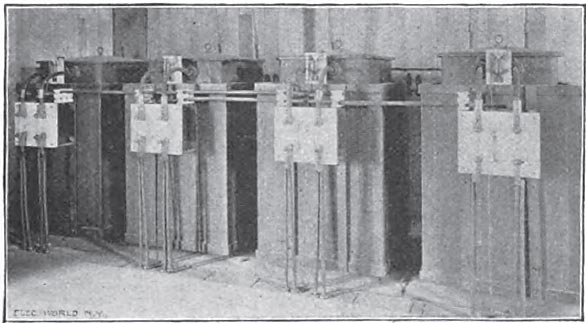
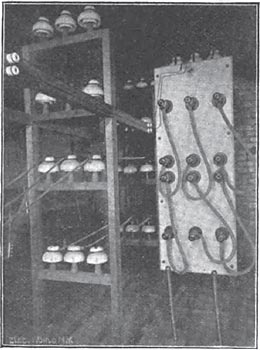
Special precautions were taken in the design of the fuses and switches for use on this high tension circuit to secure safety, as well as reliability and simplicity. The fuse terminals are enclosed in hard rubber fittings, which are supported on high tension triple petticoat insulators. The fuse is of fine wire, a foot or more in length, enclosed in a rubber tube. The contact between the fuse and the terminal is made by a screw which is entirely covered by a hard rubber cap. The high tension switchboard consists of a marble panel, with receptacles at the middle for the line terminals, and at the top and bottom for the terminals of the circuits to the step-down transformers. Connection between receptacles is made by plugs connected by flexible cable. The receptacles are entirely enclosed in hard rubber, so that there are no contacts exposed at any tame. The plugs and the cables joining them are thoroughly insulated.
Detachable wooden handles arc used for handling the .plugs when they arc to be inserted or withdrawn on a live circuit. An insulated floor or platform is arranged, on which the attendant stands when making connections on this switchboard. To prevent accident in case of a breakdown in insulation, or dampness on the surface of the plugs and handle, a special device is used to effectually protect the attendant from the current. Near the middle of the handle there is fastened a chain, which is connected to the ground, or the support of the floor on which the attendant stands.
The latter is therefore thoroughly protected, as the escaping current has two paths between the terminals of the chain, one through the low resistance metal chain, and the other through the wooden handles, the operator and the wooden platform, the resistance of the latter compared with that of the chain being so great that the attendant is effectually protected.
| |||
| High Tension Plug Board. |
This switchboard is provided with throw-over switches, by which either circuit may be thrown on either phase desired; and with fuses enclosed in lignum-vitae holders, ammeters and voltmeters. The distribution at 2000 volts is similar to that from ordinary 2000-volt dynamos. The circuits are supplied with standard transformers for reducing the current from 2000 volts to 100 or 200 volts, as may be desired. Transformers arc used for ordinary lighting work and for the supply of two-phase motors, and also by simple combinations for the supply of three-phase motors.
In the sub-station are two 50-hp induction motors, direct-coupled to 60 light D. C. series machines for supplying arc lights. These induction motors are supplied by two 75-kw transformers, which deliver two-phase current at 2000 volts.
Special attention is called to the use of a new protective arrangement, with which the high tension transformers arc all supplied, the non-arcing metal spark gap protector. This protector is connected between the low tension coil and the ground, and prevents the great rise of E. M. F. between this coil and the ground, which might occur either in the case of a breakdown of the insulation between the high and low tension coils in the transformer, or which might be caused under certain condition* by static induction between the two windings. The protector consists of a spark gap, similar to that in the well-known non arcing lightning arresters, one side of which is connected to the ground and the other side 10 the middle point of the low tension winding. The normal E. M. F. of the low-tension coil is not sufficient to cause sparking across this gap, but in the case of undue rise of E. M. F. the current jumps across this gap and connects the coil to the ground, thus affording protection from the dangers which would arise if the low tension circuit were at a great difference of pressure from the ground.
The plant has been in regular and successful operation for a year. There have been very few shutdowns, and those for brief periods only. The plant is shut down for a few minutes every Sunday morning for a general inspection and cleaning of the apparatus.
The perfect success attending the transmission of power for a distance of nearly 30 miles, involving the use of nearly 6000 insulators on a 15,000-volt circuit, is the best testimony in the world of the superior excellence of every part of the apparatus, and the extraordinary care that attended its installation. New proof is given that successful long-distance transmission is in a state of rapid transition from the field of experiment to that of practical engineering.
The Central California Electric Company was organized by Mr. Warren Van Norden, president of the South Yuba Water Company. The work is in charge of General Manager Charles Van Norden, to whom, as well as to. Mr. W. M. Probasco, of the Westinghouse Company, thanks are due for the information and illustrations contained herein. The electrical work is in charge of Mr. E. W. sutcliffe, superintendent and electrical engineer for the company.
