[Trade Journal]
Publication: Electrical World
New York, NY, United States
vol. 30, no. 15, p. 412-414, col. 1-2
The Bakersfield Power Pleat.
About 75 miles northeast of Santa Barbara in southern California there is a district which is notable in that it presents the conditions of continual verdure during the entire year. This is owing to irrigation from a mountain stream which is known as the Kern River. Hundreds of thousands of acres, however, are not irrigated nor does the Kern River supply sufficient water for this territory. An abundance of water exists, however, 20 feet below the surface, and all that is needed to extend this irrigation indefinitely is sufficient power to pump this water. Fuel, of course, is too expensive for this use, so that the only hope is the utilization of natural water power. Fortunately there is such a source of power available in the water of Kern River, some 15 miles from the district to be irrigated. The Power Development Company has been organized to develop and transmit this power to the property of the Kern County Land Company in and around Bakersfield. From a commercial standpoint the business of the Power Development Company is on a peculiarly stable basis. The company has no bonded indebtedness. Its plant was built for cash, and although it has the liberty to sell current to anyone, practically its entire output is contracted to a single consumer of the highest financial standing.
The power is developed in a station some 15 miles from the city of Bakersfield, supplied with water brought in a flume and pipe line from the mountain torrent. A full description of the plant was given in the August edition of the Journal of Electricity, from which the following information and illustrations were taken.
| |||
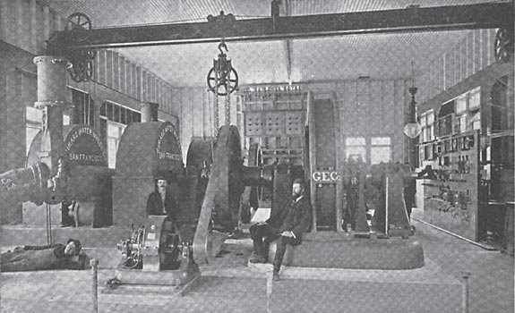
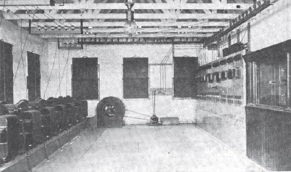
| Interior of the Generating Station. |
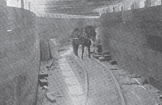
The source of water power is the Kern River, a creek in summer, and a torrential rushing mountain stream during the rest of the year. The nature of the country is extremely mountainous and rocky, the mountains being almost totally devoid of verdure of every kind. There is neither dam nor ditch at the outlet of the flume. The diversion of water from stream to flume is effected simply by means of a channel formed by blasting out the boulders. The flume itself is a highly interesting piece of engineering, because of the difficult and hazardous nature of its construction. It is built on precipitous mountain sides of extreme irregularity, and covered with rolling boulders and disintegrated rock. In spite of this the completed structure is a substantial waterway on solid foundations thoroughly shored. It consists mainly of curves which have a uniform radius of 25 feet, the longest tangent having a length of only 210 feet. The total length of the flume is 8760 feet. It is of rectangular cross section, the width inside being 8 feet and the depth 6 feet. The flume is built on a uniform grade of 5 1/4 inches per mile, which gives a velocity of flow of 6 feet per second. This; when the flume is running full, means a discharge of 288 cubic feet of water per second, which, at the effective head at the nozzles, would give 6000 available horse-power. Every precaution was necessarily taken to prevent accident to the flume from rolling boulders and rock slides. Men with crowbars went over the mountain side for the whole length of the flume and rolled down every loose boulder. The work of preliminary blasting for the grade of the flume was very difficult. The men were often held suspended by ropes from the rocks above while they drilled the blast holes, but no serious accident occurred during the entire work. Some idea of the magnitude of this work may be had front the fact that while the flume is less than 9000 feet long nearly 15 tons of dynamite were consumed in blasting for the grade. A very vigilant watch is maintained by the inspectors of the Power Development Company to discover any possible danger of breakage of the flume. To provide against any accidental break which still may occur a special trip gate has been built about 200 feet from the head of the flume. The necessity for this is due to the fact that in case of any accidental break the outflow of water might carry away the foundation of disintegrated granite and boulders, and destroy a considerable part of the flume. This trip gate consists of a vertical flash-board arrangement held suspended above the flume by means of an electrically operated trip or trigger device. The gate is faced with narrow removable flash boards, so that when closed the flash boards may be removed one by one, thus relieving the pressure of water and enabling the gate to be opened by one man. The magnetic trigger is operated over a circuit of soft-drawn bare copper wire run outside the whole length of the flume on its lower timbers front the power house. The trigger is held from releasing the gate by means of the current, so that if the copper wire is broken or short-circuited at any point, either by the breaking of the flume itself or by any inspector on the line, or by the power station attendant, the gate is closed and the water is turned off. At the same time an alarm is rung at the power house.
| |||
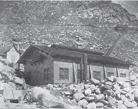
| The Power House. |
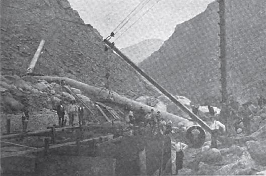
The flume is built of selected red wood timber, free from knots, and sawed on the ground, in order that it should not be injured in transportation. It is double lined, and contains throughout between the board linings a thickness of heavy P. & B. building paper, applied with hot asphaltum at the scams to insure waterproofing. The amount of lumber used in the flume was 967,000 feet. About 200 feet below the trip gate is a sectional trap gate placed at the bottom of the flume for draining the latter, and relieving it of such water as may leak through the head trip gate when closed. A short distance further down is located the sand trap, consisting of an adjustable opening in the bottom of the flume in the lower end of 50-foot section, which has its bottom 7 inches below that of the rest of the flume. At various points along the flume are located three side gates of usual form, and near the forebay are a spill way and waste gate. Equidistant along the flume are four telephone booths leading up each other and to the power house. Near the forebay is located a water gauge, for showing the height of water in the flume. The characters on the gauge are discernible to the naked eye from the power house far below by day, and at night the gauge is illuminated by incandescent lights, there being a white lamp at each foot mark, and a blue lamp on the traveling index. From the forebay to the power house in the valley below the water is carried in a pipe line 540 feet long, with an inside diameter of 66 inches. The maximum head on the bottom of this line is 202 feet. The maximum gradient is approximately 54 per cent. The thickness of the pipe shell varies from No. 12 B. W. G. to three-eighths of an inch. The pipe was tested after being laid, and no leaks were discovered. It was then covered with a heavy coat of P. & B. paint, and buried in earth well tamped in with water, to make a solid and substantial bed. The earth filling completely covers the pipe, except about one-sixth of its surface at the top. The pipe discharges into a receiver at the power house, 6o feet long and of a diameter of 66 inches. It is built of steel plate five-sixteenths of an inch in thickness, and ends in a header of half-inch steel with a manhole in its centre. Attached to it by a la-inch nozzle is an air chamber, 30 inches in diameter by 16 feet long. Under the receiver there is also attached a 6-inch nozzle and blow-off valve.
| |||
| Laying the Pipe Line. |
| |||
| Within the Flume. |
Water is supplied to the water wheels through three cast iron saddles attached to the receiver, from which three goose necks are tapped off. Two of these goose necks lead to water wheel units, the third being provided with a view to future extension.
The prime movers consist of two sets of 44-inch Girard water wheels, each set containing two wheels, as shown in the illustration. These wheels are direct-coupled to each other and to the generator, the exciter for each combination being belt driven from the fly-wheel governor. Each water wheel set is provided with a 20-inch gate, operated direct by an hydraulic cylinder. The governor actuates a similar hydraulic ram which controls the seven nozzles of each wheel of the set, and at the same times opens or doses, as the case may be, a compensating by-pass valve, the rear of which is shown in the illustration, just beyond the main valve. The effective head of water at the wheels is 192 feet, and the by-pass valve is provided to prevent any sudden shocks due to the shutting off of the flow of water in the long pipe line. The wheels run at 257 revolutions per minute, and are controlled by Girard governors. The rams were originally operated by water from the pipe line; but during certain seasons of the year the water is so gritty as to cut the valves, to avoid which the rams are now operated by oil under air pressure. This oil and air is supplied by a combination pump, which is driven by belting and gearing from the main shaft. The water wheels generate 750 horse-power per set, and drive General Electric 450-kw, 550-volt, 60-cycle three-phase generators.
| |||
| High-Tension Switchboard. |
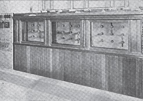
The exciters are two General Electric 17 1/2-kw, four-pole, 125-volt dynamos, running at 1100 revolutions per minute. The generators may be run independently, or in multiple, being provided with two sets of bus bars on the switchboard. From them the current is carried to two transformer panels, consisting of main switches and ammeters for each set of step-up transformers. These consist of General Electric air-blast machines, there being in each set three 160-kw transformers, taking the current at 500 volts and delivering it to the line at 11,500 volts. The primary and secondary windings of the transformers are in delta connection. A seventh transformer is held as a reserve. The connections on the high-potential boards at the power house and also at the sub-station are quite novel. All the high-potential switches used in the installation are of the familiar quick-action type of the General Electric Company, having 12-inch breaks. The three panels of the high-potential board contain three sets of double-pole double-throw switches. Beside this there is a multiple panel which contains one set of triple-pole single-throw switches. By means of these switches any desired combination can be effected of the different transformers in the different sides of the delta of the different machines and on the different lines. From the high-potential board the circuits proceed through the lightning arrester equipment to the line. The Wirt arrester is used in this system. Each leg of each three-phase circuit has two marble panels on each of which are fifteen brass cylinders, measuring 2 inches each way, and separated one thirty-second of an inch. These two panels are coupled in multiple and grounded through four graphite rods, each three-quarters of an inch in diameter and 12 inches long, and having a resistance of approximately too ohms. This interposes in the ground circuit, therefore, about 400 ohms. A choking coil is also interposed between the lightning arrester and the line, consisting of two rings, each about 20 inches in diameter, wound with 150 feet of No. 4 wire, connected in series and independently supported on high tension porcelain insulators.
| |||
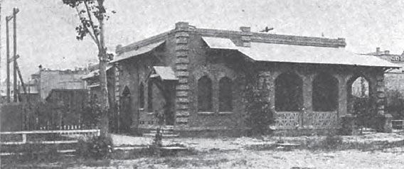
| The Sub-Station in Bakersfield. |
The pole line also differs somewhat from conventional practice. Short poles are used on the level unfrequented country traversed. The length is 26 feet over all. They are placed 25 feet apart, and carry the two three-phase circuits of No. 4 B. & S. bare copper wire. Two wires are carried on a short cross arm and four wires on a longer cross arm at a lower level. Two three-phase circuits are arranged to form each an equilateral triangle 24 inches on each side, the wires being the apexes of these triangles. The transmission is transposed at every mile, the transposition spans being 80 feet in length. Six-inch General Electric triple petticoat porcelain insulators are used throughout on the high tension line, the total length of which is approximately 14 1/2 miles. A separate line is tapped off at Bakersfield, and runs to Stockdale, to miles away, making the total length of transmission actually 25 miles.
| |||
| Interior of Sub-Station. |
The high-tension transmission lines run into a number of small sub-stations, which are uniformly equipped with 15-kw special "Type H" natural-draft transformers. In these transformers the primary coils are insulated from one another by thick layers of felt. Between the coils of the primary and secondary winding there is an air space of one-half inch. The whole is mounted upon a solid iron foundation, securely braced, and is covered with a corrugated iron cylinder, provided with a ventilating roof. From these transformers current is supplied for lighting and power purposes, the motors varying in size from 2 horse-power to 75 horse-power, all of the induction type. The pumping stations consist of plain but substantial houses, containing an induction motor belted to a single centrifugal pump. The pump outlet empties into an irrigating ditch of the usual form.
