[Trade Journal]
Publication: Electrical World
New York, NY, United States
vol. 30, no. 15, p. 414-417, col. 1-2
The Electrical Power Transmission Plant at Three Rivers, Quebec.
BY H. R. LEYDEN.
The first long-distance electrical-power transmission plant to be installed in Canada has now been in operation for six months with most satisfactory results, both from the engineering and financial standpoints. This plant was installed by the North Shore Power Company to transmit power from the waterfall at Grande Chute on the Batiscan River over a distance of 17 miles, to the city of Three Rivers. The present development delivers boo horse-power at the end of the transmission line, but the plant has been laid out with the view of largely increasing this for future demands. The most interesting feature in connection with this transmission plant is the novel method in which the two-phase power is applied to an old electric-light plant, which formerly operated single-phase alternating apparatus and a series-arc system by steam power. The new power is applied to the old system with surprisingly few changes in the distribution.
| |||
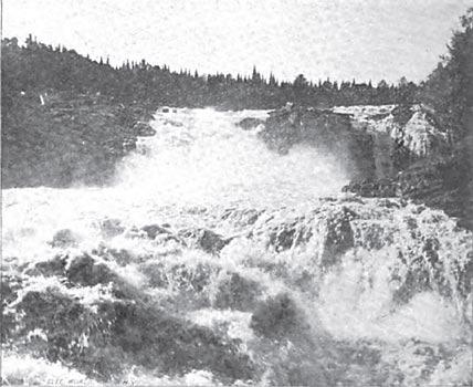
| Grande Chute, Batiscan River. |
The old plant consisted of two single-phase alternators of 1500 and 750 incandescent lamps capacity, and of two series-arc dynamos, one of thirty-five and the other of fifty lamps capacity. All the dynamos were belted directly to high-speed steam engines. There was also a suitable boiler plant using bituminous coal for fuel. In connection with the electric-lighting plant there was a pumping plant capable of delivering 1,000,000 gallons every twenty-four hours to supply water to the city. Both the lighting and the pumping plants were owned by the municipality of Three Rivers, which had operated them for over six years. A careful system of accounting has shown, however, that, even with higher rates for service than are charged elsewhere by private companies, this municipal plant was running behind every year. The city authorities, therefore, decided to dispose of the plant, and stop the continued outlay caused by the yearly deficits in their lighting and pumping account. The plant was accordingly sold to the North Shore Power Company at a large reduction from its original cost and a contract was made with the company for supplying the street lighting and pumping service required by the city at rates customary in cities of this size and character.
The company, in order to reduce the cost of such service, decided to employ water power, which is quite plentiful in this portion of the Province of Quebec. The most available powers were at considerable distance from the city, and the cost of transmission was at first thought to be too great, but a careful investigation showed that, in utilizing the Grande Chute of the Batiscan River, the cost of the transmission line would be comparatively small, and that the necessary investment for the hydraulic and electrical plant would pay a very good return.
|
| |||
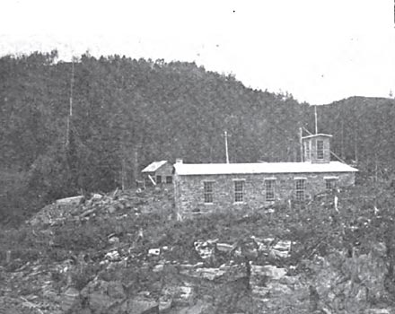
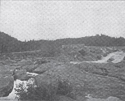
| General View of Power House and Flume. |
This beautiful waterfall was almost ideal for a development of this character, as the waters of the Batiscan at this point tumble over rocky ledges, giving a total fall of 60 feet within a distance of too yards. The Batiscan River has a large and regular flow of water at all seasons of the year, being fed by large lakes a long distance back in the Laurentian Mountains. The power of the whole fall is estimated at over 3000 horse-power, but only a portion of this is utilized by the present plant. In addition to this large and constant flow of water, this fall has the particular advantage of being free from a bugbear of all water-power plants in told climatesfrasile. This is a peculiar ice formation differing from both anchor ice and slush ice, and more dangerous to water wheels and racks than either, as it often sinks below the surface of the water, especially if the current is swift. It forms only in open water, and rises to the top if there is little motion, so that the only reliable method of avoiding its dangers is to have a large body of still water above the dam. Immediately above the Grande Chute the water is quiet and covered with ice in winter for 1 1/2 miles up stream, so that there is no fear from this source.
| |||
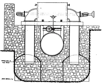
| Turbine, Penstock and Draft Tubes. |
This magnificent power seems to have been designed by nature for the purpose to which it is now being put. Nearly all the dam work for its utilization had already been done by some volcanic upheaval, so that it only required the expenditure of a little over $1,000 on masonry work to render the large, natural force of this power available in a very convenient form.
It may be seen from the illustrations that only a short length of masonry was necessary to form the dam and head-gate construction. The stone for this work was procured on the spot by blasting away portions of the ledge, and the dam was built directly on the granite rock which formed the crest of the fall. The artificial dam only extends half way across the stream, the other part being a natural spillway.
| |||
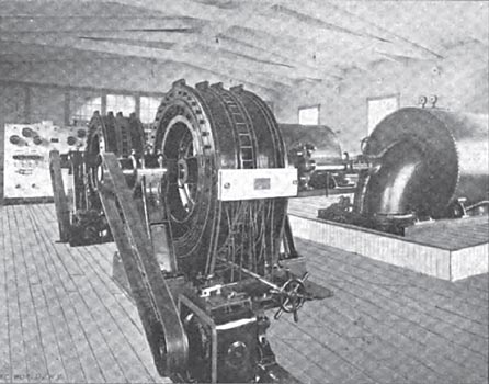
| Interior of the Power House. |
From the head gates the water is conducted in a steel flume down through a natural trench directly underneath the power house, a distance of 400 feet. The flume is 6 feet 6 inches in diameter, and is built up in 6-foot lengths of one-quarter inch boilerplate,supported by piers every s feet. It is the intention to cover the flume before cold weather sets in with spruce boughs, over which the snow will make a protective blanket against the intense cold of winter.
The power house is a substantial stone structure built on a flat ledge of granite. It is 62 feet in length by 36 feet in width, and is designed in such a way as to allow an increase of the present equipment as the demand for power grows beyond the present installation of 800 horse-power.
The lower end of the steel flume terminates in a large head sheet, which is provided with a gate valve for drainage when the water is shut off. A few feet from the lower end, and directly beneath the wheel cases, the water for the turbines is taken from the feeder or flume by two branch pipes which lead vertically upward, and connect through shut-off gates with the wheel cases.
The wheel cases are placed on the power-house floor, supported by iron girders set in heavy stone walls. They are built of 5-16-inch boiler plate 6 feet in diameter, with heavy cast iron heads, terminating in quarter-turn elbows 30 inches in diameter, each of the elbows forming the discharge of one of the turbines and providing a bearing for the shaft which runs entirely through the case. The wheels are 20 inches in diameter, two being mounted on each shaft and arranged so that they discharge in opposite directions, thus equalizing the thrust. Two of these 20-inch wheels give over 400 horse-power under a 50-foot head, running at 400 revolutions.
The wheels are of the Crocker type, and they, together with the flume and head-gate work, were supplied and installed by the Jenckes Machine Company, of Sherbrooke. Quebec.
The two electric generators are of the "S. K. C." two-phase type, of 240-kw capacity. They were supplied, together with the rest of the electrical equipment, by the Royal Electric Company, of Montreal. The generators are connected directly to the turbine shafts by means of flexible insulated couplings. These couplings are made of sole leather links, which connect projecting pins on the generator and turbine halves of the coupling. They have proved to be extremely satisfactory in service, even when the shafts have not been in true alignment. The exciters, of which there is one for each machine, are belted to the free ends of the generator shafts.
The current is generated at a pressure of 2400 volts, with a frequency of 16,000 alternations per minute. This periodicity was adopted because the electrical distributing apparatus at Three Rivers was designed for this number of alternations, and it was not considered advisable to alter it. A neat switchboard of white marble has been installed to properly regulate the generators, which are designed to operate in parallel. From the switchboard the current is carried to the step-up transformers, where the pressure is raised to 12,000 volts.
| |||
| Step-Up Transformers and High-Tension Switchboard. |
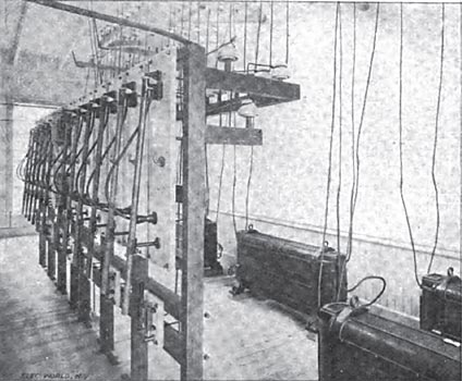
The transformers are placed in a separate room, which is divided from the main room by a glass partition. The transformers are in 6o-kw units or four for each phase of the plant; they are of the self-cooling type, using neither air blast nor water to keep the temperature down. The primary and secondary coils of each transformer are controlled by separate switches, so that they can be readily thrown in or out of service as required. The switches on the 12,000-volt side are of the "S. K. C." non-arcing plug type, as can be seen from the illustration; these switches will break a 12,000-volt arc effectively, with no danger to the operator or the switch. The 2400-volt switches are of the ordinary jack-knife type. On the step-up transformer board there are also placed two static ground detectors; they are for indicating any grounds on the transmission line, and are connected directly to the high-pressure wires. From this board the wires are led on porcelain insulators to the cupola of the building. The interior of the power house is painted white throughout, and presents a clean and cheerful appearance.
From the power house the transmission line leads directly up the side of the mountain, and thence off on almost a straight line to Three Rivers.
The transmission circuit consists of four bare copper wires of No. 4 B. & S. gauge. This transmits the full power of the two generators over the 17 miles with a total drop of 10 per cent., of which a little more than 2 per cent. is due to induction. The poles used are of white cedar, 35 feet in length and 6 inches in diameter at the top, set 5 feet in the earth. The wires are placed 18 inches apart and supported on special high-voltage porcelain insulators. Considerable difficulty was experienced in procuring insulators suitable for this work; the requirement was that they should stand a voltage stress of 40,000 volts for five minutes when placed in a salt-water bath with the hole for the pin also filled with salt water. The first lot supplied almost all failed in the test and were not accepted. Another manufacturer, however, supplied insulators, of which less than 2 per cent. failed under this test.
The pins supporting the insulators are made specially tall, to keep the wires free from wet snow, which falls heavily in this region.
This line construction gives very satisfactory results. The only accident occurred on the first night of its operation, when a limb of a tree got across the wires, the result being that the limb and the wire were both burned off. Since then there has been no trouble whatever.
On the top of the poles and at each end of the cross arms are fastened lines of ordinary barbed fence wire for lightning protection. These wires are attached with ordinary staples and grounded at every sixth pole, by means of a galvanized iron wire extending down through an iron pipe planted beside the pole. This lightning protection is supplemented by banks of lightning arresters at each end of the line. This method of protection has proved itself thoroughly efficient during the past summer, when numerous electric storms occurred without causing any trouble.
| |||
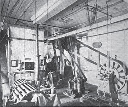
| Sub-Station at Three Rivers. |
A telephone line, which is not shown in the cut, was afterwards strung, using ordinary galvanized iron wire attached to side brackets below the cross arms. Ericsson anti-induction instruments are used, and no annoying humming is experienced.
The line crosses the St. Maurice River on the highway bridge just outside the city of Three Rivers. Here the ordinary cross-arm construction, built out from the side of the bridge, is used. The wires run directly to the power house at Three Rivers, which is now used as a distributing station. Here step-down transformers reduce the pressure to 1100 volts, which is the voltage formerly employed in the old lighting service. A transformer board, similar to the one in the power house at Grand Chute, is used to cut in and out each individual transformer. The transformers supplying the incandescent system are made with regulating secondaries, so that the voltage on the lighting circuits can be controlled at the distributing station as well as at the generator. The old incandescent circuits were attached just as they were, no change of any character being necessary. The employment of 16,000 alternations in the new plant allows the use of the old transformers, while a lower frequency would have necessitated a change to new ones designed for the lower periodicity.
| |||
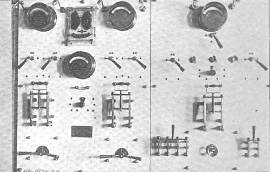
| Distributing Switchboard. |
The arc-lighting service was formerly supplied by two Royal arc dynamos, shown in the left of the illustration, belted direct to the engine pulleys. The new arrangement uses the old 1500-light single-phase alternator as a synchronous motor, operating from one phase of the two-phase circuit to drive the arc machines. The other parts of the arc system, including the switchboard, connections, circuits and lamps, remain the same. The dynamos were not even moved from their former position, so that in case of accident to the water power the old belts can be put on, and the plant operated by the steam engine, as before. All that was required to accomplish this change was to place a shaft overhead to which all machines are belted and to install a 10-hp induction motor to bring the alternator into synchronism with the generators at the power house: Clutch pulleys are used for driving the arc machines, so that the starting motor only has to start the synchronous motor and the shaft. When the synchronous motor is brought to speed, the current is thrown on, and it immediately takes the load, allowing the starting motor to be shut down. The arc dynamos are then thrown into service with the clutch pulleys, and the arc lamps operated as usual. This is another reason for employing 16,000 alternations, for, if a lower periodicity had been employed, the old alternator, being a 16,000-alternations machine, could not have been used for this purpose.
It is found that 60 kilowatts delivered from one phase of the generator will supply all the loss in transmission, the losses in the motor, shafting and arc machines, and operate seventy-eight 12000-cp lamps over their circuits 4 miles in length. The simplicity and economy of this method of operating an old plant is strongly in favor of the flexibility of the two-phase system for transmission work.
The switchboard used at the distributing station is composed of two panels of white marble, having the instruments mounted on the marble; the right-hand panel is for the synchronous motor. The amperemeter at the top is provided with a short-circuiting switch, so that it can be cut out when the plant is in operation; it is only used for the purpose of properly adjusting the field of the synchronous motor, so that it takes the least amount of current. If over or under excited, it would produce leading or lagging currents. Below the amperemeter is a synchronizer of the ordinary three-lamp type, and on either side may be seen the handles of duplex fuse blocks, which are on the back of the board. They are provided with two fuses each, so that if one should blow, by throwing 'this handle the other is immediately cut into service. Below are shown the main switch, the field switch, exciter rheostat and the four-pole, two-phase, starting-motor switch. The left-hand panel shows the incandescent distributing board. It is for two circuits, such being the old distribution.
The pumping, which is done in the same building, was formerly performed by a duplex steam pump. This plant is now being replaced with two triplex double-acting power pumps, each driven by a two-phase motor. One of these pumps will be sufficiently large for the ordinary service, but the second will be started in case of fire or any extra call for water. The water will be pumped directly into the mains, no reservoir or gravity pressure being employed. To provide' the variable flow required, the discharge pipes of the pumps will be provided with relief valves, so that whenever the pressure in the mains exceeds the prescribed limit the extra water will return to the suction pipes.
These simple arrangements will enable the company to carry on all the lighting and pumping service of the city by means of the water power 17 miles distant, and to close down the steam plant entirely. The steam plant, however, will still be retained in case any accident should interrupt the water-power service.
The changes above described have been accomplished with no interruption of the old service, and have utilized all the old electrical apparatus except the no-light alternator, which is now not required. No expense whatever has been involved in changing the distribution system to accommodate it to the two-phase current transmitted from the water-power plant. The service of the arc and incandescent systems has been greatly improved by the change.
