[Trade Journal]
Publication: Electrical World
New York, NY, United States
vol. 30, no. 15, p. 407-409, col. 1-2
CANADA is a region of gigantic water powers, which have waited for the advent of electricity to he utilized for the many purposes to which they are applicable. Perhaps the fittest installation for the development and transmission of the power of falling water extant is that of the Chambly Manufacturing Company. at Richelieu Village, Quebec.
At this point, about 25 miles distant from Montreal, the Richelieu River falls through a long series of rapids. From early days a wooden dam between Richelieu Village on the one side of the river, and Chambly on the other, has been in existence, supplying power to a few small mills. The new structure which takes its place is one of the finest examples of hydraulic engineering on the continent, consisting of a massive concrete dam, in which, as an integral part, is built the power house, with a capacity of 20,000 horse-power.
| |||
| The Chambly Manufacturing Company's Electrical Power Transmission Plant. |
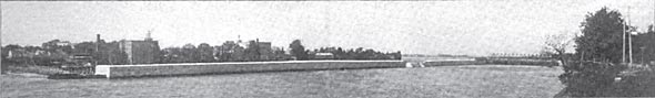
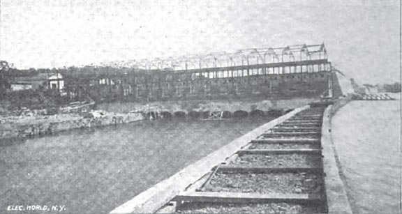
This dam, which is shown in the initial illustration, is about anon feet long, 6 feet wide at the crest, and constructed of a concrete composed of the broken rock of the river bed, mortared with sand from the vicinity and American cement. The back is vertical throughout, and the apron is curved so that the overflow water is discharged horizontally, obviating any destructive washing action at the base. A liberal use of one-half inch iron rods, incorporated with the mass of the concrete, gives great strength to the structure, and a surface dressing of neat cement insures the greatest impermeability. This is said to be not only the most carefully constructed but also the largest concrete dam on the continent.
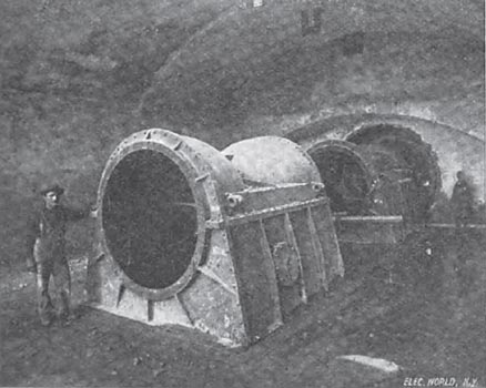
The dam consists of three portions, two of which run perpendicularly across the course of the river, while the third and middle part is parallel with it. In the lower third of the dam, and near the right batik of the river, is built the power house. Here the dam consists of two levels, or steps, over which is built a structure of steel beams and brick walls, 308 by 51 feet, for the protection of the machinery. The upper level, which is about 2 feet above the surface of the water in the lake formed by the dam, will contain the switchboards and controlling devices and such offices as are necessary. In this part of the dam eight rooms, or flumes, each about 20 feet square and to feet high, are constructed, their arched openings being under the water level, for the reception of the wheels. These, of the horizontal-shaft pattern, number four in each flume, each wheel being 46 inches in diameter. These wheels are mounted tandem on one shaft in two pairs, between the wheels of each pair being a large cast-iron box communicating with the draft tubes, which extend through the solid concrete of the lower step of the dam to a point below the level of the tail water. The draft tubes are built of sheet steel, and are 9 1/2 feet in diameter where they leave the boxes, and 10 feet at their outlet. The upper extremities of these being one behind the other in the line of the shaft, necessitated their construction in a curious skew curve. This installation seems to run to superlatives, since these draft tubes are the largest ever constructed. Their bedding in concrete excludes all possibility of leakage, and it is confidently expected that the full advantages of the head of 28 feet will be realized by their use, although the wheels are but a few feet below the level of the intake water. Under this head. and at the speed of 153 r. p. m., each wheel will develop660 horse-power, or a total of 2640 horse-power to each shaft and flume.
| |||
| The Waste Gate From the Fore Bay. |
The governing of the wheels will he by means of Giessler electromechanical governors, similar to those in use at the Lachine plant. These are relay governors, the revolving balls actuating a small lever which closes electrical contact at speeds higher or lower than that for which the instrument is set. These contacts control electromagnets which operate clutches on the main shaft geared to the gate of each gang of wheels. It has proven an excellent and reliable governor in other large hydraulic installations, notably in that at Lachine Rapids, described in THE ELECTRICAL WORLD of October 2.
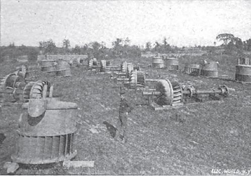
At present only four of the eight sets of wheels are being installed, together with two 28-inch wheels, giving 750 horse-power for driving the exciters of the large dynamos. The whole of the hydraulic machinery was furnished by the Stilwell-Bierce and Smith-Vaile Company, of Dayton, Ohio, and reflects much credit upon that concern by the solidity of its construction and the great accuracy with which the parts of the heavy wheels and draft tubes were assembled at Chambly by its constructing engineer, Mr. H. A. Wright.
| |||
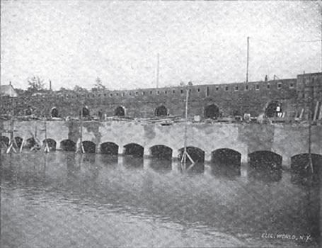
| Two-Step Dam From Below, Showing Tail Races and Flume. |
The shaft of each gang of turbines passes out horizontally through a circular steel bearing plate on the down-stream vertical face of the upper step of the dam, and is directly connected to a 2000-kw generator, giving two-phase current at 60 cycles per second and 12,000 volts.
These machines are of the inductor type, having no moving wire. The inductor is about to feet in diameter, and of very massive construction. The single-circular field coil is wound on a brass spool of about to inches face by an equal depth, and completely surrounding the inductor. The armature is in two parts. The insulation of these armatures is necessarily most massive and substantial. All the dynamo machinery is now under construction by the Royal Electric Company, at Montreal, front designs by the Stanley Electric Manufacturing Company, of Pittsfield, Mass.
In the space above the flumes in the upper portion of the power-house dam, a large conduit has been made for the reception of the leads from the dynamos to the switchboard Lead-covered, tubber-insulated cable will be used for these. In the walls of the power house a number of large terra-cotta pipes, about 3 feet long, bent to a quarter circle, with the convexity upwards, have been built in, and through these the cables leading to the pole line will pass out without touching anything between the insulators inside and outside the building.
| |||
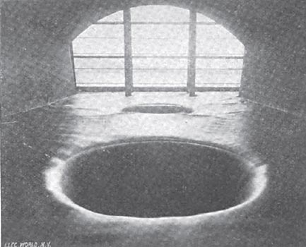
| Flume and Draft Tubes Before Turbines Were Set. |
Two pole lines will be constructed to Montreal, either one being sufficient to carry the load. This construction was adopted to minimize the chances of accidental breakdown, and to make repairs easily possible without danger to workmen. The poles are of chestnut, none being less than 40 feet long. Each pole carries two cross arms, the usual "square" for two-phase transmission being observed. The insulators are of a deeply petticoated porcelain type, somewhat similar to the Niagara pattern, but lacking the grooves for conducting away rain water. They are mounted on oak pins, having a steel rod in the centre of each. A line of barbed wire is run along the tips of the poles, and four similar lines are attached at the ends of the cross arms, all five being connected together and grounded by means of 8 feet of iron gas pipe at each pole. The line wire is bare, of 00 gauge, and is tied to the insulators by two pieces of No. 12 gauge soft copper wire. A short distance below the main line a short cross arm carries the two No. 12 copper wires of a telephone circuit.
| |||
| Casings for Four Turbines in Place in Flume. |
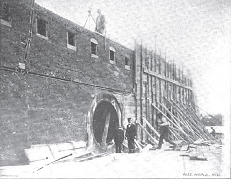
| |||
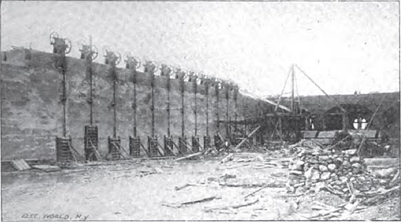
| Building the Upper Step of Power-House Dam, Showing Manhole to Flume and Entrances to Cableways. |
The main power transmission line will end in the electric light station of the Royal Electric Company, at Montreal, where 6000 horse-power will be used for incandescent and arc lighting and direct-current motor service. The large two-phase generators now employed in that plant for incandescent lighting and power will be rewound as synchronous motors, and connected directly in the 12,000-volt circuit. These machines will then be belted by a system of countershafts to the arc-light generators and other continuous-current machines of the station, to which they will furnish power. A group of static transformers of 150 kilowatts each will be arranged in the basement of the present station, reducing the line voltage of 12,000 for distribution over the present circuits at 1000 and 2000 volts, two-phase.
| |||
| Looking Down Lower Step of Dam. Power-House Framing. |

| |||
| Looking Up the Tail Race Towards the Power House. |
These transformers are now under construction at the works of the Stanley Electric Manufacturing Company, in Pittsfield, Mass. Their greatest feature of novelty is in the method of cooling employed. The transformer is set up in an iron case in the usual way, this being filled with oil for insulation, and the whole surrounded by a sheet-iron water jacket. As the plant in Montreal is some feet below the level of the Lachine Canal, from which water is obtained under a small gravity head, the water going to the condensers will be allowed to circulate around these transformers in the jackets, and it is expected that this arrangement will result in very effectual cooling.
| |||
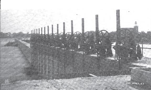
| A Few of the Turbines. |
The troubles with ice, which have been for so long a bugbear to many Canadian plants, are not expected to be at all serious at Chambly. The back water from the great dam will make a lake of still water at least 1 1/2 miles long up the river, and, as this will freeze over the surface at the beginning of the season, no trouble whatever is expected from anchor ice. It is expected that floating ice in the spring thaws will clear the darn without trouble. It is a peculiarity of the Richelieu River, which is the outlet to Lake Champlain, that its current is comparatively steady throughout the year, and consequently no difficulties with freshets or low water are anticipated. The construction of the dam and other elements of the power development reflect great credit upon the engineer of the Chambly Manufacturing Company, Mr. J. G. Macklin. The work is progressing at an extremely rapid rate, and the contracts call for the installation of all the hydraulic machinery and the completion of the dam by January 1 next. One of the dynamos is finished and the others are well under way, so it is likely that current will be turned on from this installation in the early spring.
| |||
| Waste Gates. |
It is expected to deliver nearly 20,000 electrical horse-power from this plant in Montreal when the total equipment is installed at Chambly. This will make a grand total of nearly 40,000 horse-power sent to that city from two great water powers.
