[Trade Journal]
Publication: The Electrical Engineer
New York, NY, United States
vol. 19, no. 361, p. 312-314, col. 1-2
MISCELLANEOUS.
THE LOMBARD WATER WHEEL GOVERNOR.
AS APPLIED TO THE POWER TRANSMISSION PLANT AT BALTIC,
CONN., FOR THE PONEMAH MILLS AT TAFTVILLE AND
THE NORWICH STREET RAILWAY.
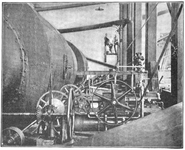
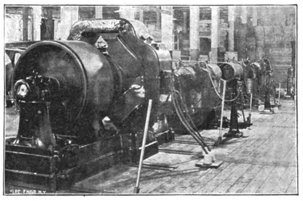
The recent installation in the power house of the Baltic Power Co., at Baltic, Conn., of a Lombard water wheel governor, has solved a difficulty which was rapidly becoming almost insuperable. In our issue of May 2, 1894, we described this plant as it existed about a year ago, when the three-phase current generated at Baltic was carried about four and a half miles to Taftville where it was utilized solely for driving the machinery of part of the Ponemah Mills in that town. Since that time, however, Mr. E. P. Taft, the progressive founder of the Taftville cotton industry, has added the Norwich Street Railway and a 500 H. P. electric locomotive to the load of the Baltic Power Co., and the extreme fluctuations of the railway current made such a varying demand on the generators at Baltic, that the question of governing the turbines became of paramount importance. Every conceivable method was tried, but all without success, until the Lombard governor was installed a few weeks ago, since which time, the speed has been almost constant, no matter what the fluctuation of the load may be. It is not too much to say that this machine is practically perfect, and seems to almost anticipate any change of load. Probably the most severe test that this governor is put to is at noon and at six o'clock in the evening when the Ponemah Mills shut down, at which time about 400 H. p. is suddenly shut off, and the street railway circuits, with a maximum of about twenty to thirty cars, are left on. At these times the speed will increase only a revolution or two and in a very few seconds the governor has the work again in thorough control. Fig. 1 shows the governor at work, geared to an 800 H. P. P. C. Holmes horizontal turbine. This governor is manufactured by the Lombard Water Wheel Governor Co., of 61 Hampshire St., Boston.
| |||
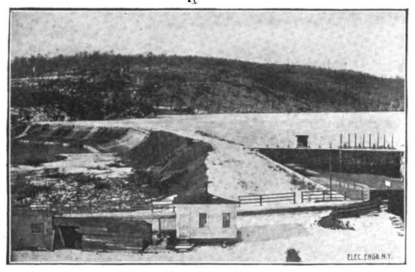
| Fig. 2. Dam of Baltic Water Power Co., Baltic, Conn. |
Before describing the details of the Lombard governor, perhaps the best and the most graphic method of showing what it is capable of is by means of the diagram shown in Fig. 3 which represents readings of load and speed taken at frequent intervals when in actual service at the Baltic Power plant.
This diagram shows the load in horse power from 6.20 P. M. to 6.50 P. M. on March 6, 1895. The figures at the bottom of the diagram represent minutes, those at each end of the diagram represent load in horse-power; and the irregular line shows the variation of load each half minute. For convenience the load in horsepower is indicated by figures where the load crosses the vertical lines, that is at half minute intervals. The figures parallel with the load line show the variation in load each half minute. Thus, at 6.27 P. M. the load was 57 H. P.; one half minute later it was 278 H. P., showing an increase of load of 216 H. P. in half a minute; at 6.28 P. M. the load was 446 H. P., showing an increase of 173 H. p. in half a minute, or a variation in load in one minute of 216 +178 = 389 H. P.
By following the vertical lines to the top of the diagram the variations in speed may be seen. The dotted line shows the speed at which the wheels should have run and the full line shows the speed at which they did run. The figures above the speed line show the revolutions per minute of the tachometer shaft; and the figures below the speed line show the per cent, variation from normal speed.
| |||
| Fig. 1. Lombard Water Wheel Governor in Power House of Baltic Power Co., Baltic, Conn. |
Thus at 6.27 P. M. the speed was one per cent, higher than it should have been. One half minute later, the load having increased 216 H. P. the wheel speed was just right; one half minute later (6.27 1/2) the load now being 889 H. P. greater than one minute previous, the speed is one per cent, below what it should have been. The greatest variation may be seen at 6.31 1/2 P. M. when the speed was two and one-tenth per cent, higher than it should have been.
An interesting example, showing how this governor will bring a wheel to normal speed under a wide but continuous variation of load, may be seen at 6.32 1/2 P. M. Here the speed was two-tenths of one per cent, over normal speed. A heavy load begins to come on rapidly; the speed first falls five-tenths of one per cent, under speed and then rapidly comes back to where it should be, so that at 6.34 P. M. the speed is just right though ,the load has increased 397 H. P.
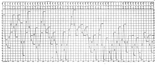 |
| Fig. 3. Diagram of Load and Speed Taken From the Plant of the Baltic Power Co., Baltic, Conn. Note. the Figures Showing Per Cent Variation Are Decimal Parts of 1 Per Cent., Not Whole Per Cent. |
The diagram shown in Fig. 3 was purposely taken between 6.20 and 6.50 P. M., when the mills at Taftville were shut down and the load consisted solely of the Norwich Electric Railway and the electric locomotive the railway load alone being much more difficult to govern than the railroad and the mill combined. It should be added that one small incandescent machine is also driven from the jack shaft at Baltic, and no unpleasant variation in the lights is noticed.
After having thus seen what the Lombard water wheel governor will do, it will be interesting to know something of its construction, and the means by which it accomplishes its object.
| |||
| Fig. 4.260 K. W. Three-Phase Motors, Ponemah Mills, Taftville, Conn. |
The Lombard water-wheel governor consists essentially of an hydraulic piston which applies its thrust in either direction to the rack, pinion and gears, which gears transmit the motion of the piston to the gate mechanism of the turbine. The actuating force which operates the hydraulic piston is air compressed under about fifteen atmospheres (210 lbs. gauge pressure). This air is contained in the cylindrical tank under the bed plate of the governor and the pressure is maintained by a pump operated by the band wheel shown at the back of the machine in Fig. 1. The pressure tank is about one third full of a thin non-viscous oil and the piping is such that oil, and never air, enters the hydraulic cylinder. It will be noticed that about one-third of the distance from the left hand end of the pressure tank there is a row of rivet heads. At this point there is a tight partition across the tank and there is no connection between the right and left hand end of the tanks except by way of the piping and through the hydraulic cylinder. In the right hand end of the tank are oil and air under high pressure, and in the left hand end of the tank is a vacuum. The piping is such that the oil is discharged from the hydraulic cylinder into the vacuum tank and is immediately returned by the pump to the pressure tank. In this way a constant pressure and a constant vacuum are maintained. In other words, the oil circulates under pressure in a closed system without any access to atmospheric pressure. The circulating system is provided with a lever throttle valve and globe valves at various appropriate points; also pressure and vacuum gauges.
| |||
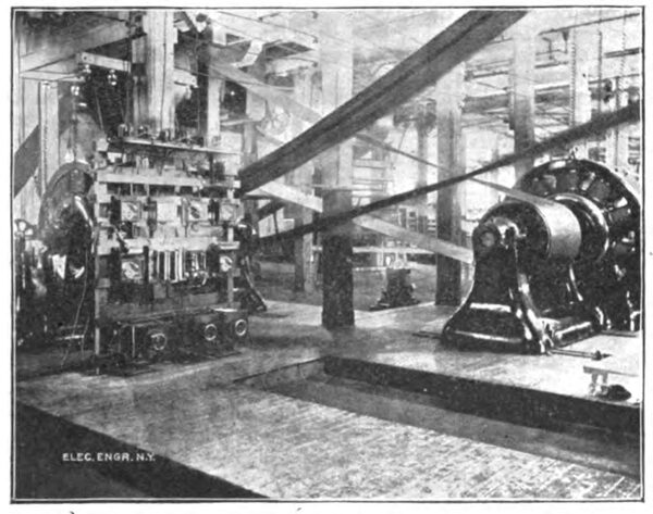
| Fig. 5. Railway Generators Driven by 3 Phase Alternating Motors. |
The centrifugal governor balls actuate a perfectly balanced piston valve which stands in the circulating system. This valve as a lap of one sixty-fourth of an inch, and a motion of that amount one way or the other, as the speed varies, causes the hydraulic piston and train of gears to open or close the gates of the turbine. The mechanism of the valve motion is such that the full amount of motion due to the position of the balls is not used ; in other words, the governor does not continue opening or closing the gates of the turbine until the centrifugal balls have resumed their normal position, but stops at such a position that when the various inertia forces have been absorbed, the turbine gates will be in the proper position for the new load.
This peculiar motion of the valve is positive, automatic and adjustable, and gives perfect control of the turbine no matter how great the variation of load. By this it is not meant that this governor will hold a wheel to an absolutely constant speed, but it gives a speed regulation that compares favorably with the best steam engine practice, and marks the beginning of a new era in the art of generating power by turbines.
Having described fully the method of controlling the speed at the Baltic power plant, a short description of the plant at Baltic and the driven plant at the Taftville end will be interesting, especially as considerable modification of the original plans have been made. The experience gained in running this three phase plant, one of the first important ones in the country, is exceedingly valuable to others either using or contemplating the use of this method of distribution.
The water power of the Baltic Power Co. is obtained by damming the Setucket River at Baltic, the dam, Fig. 2, being 81^ feet high and 500 feet wide, with an estimated available horse power of 1,600 average throughout the whole year. The wheels consist of two 800 H. p. and one 800 H. P. horizontal double turbines, manufactured by the P. C. Holmes Co., of Gardner, Me., and run at 150 revolutions per minute. The turbines are belted to a 7 inch eUel shaft, supported on an iron frame work, resting on granite piers, and running at 800 revolutions per minute, the driven pulleys being on quills. The two generators, situated in the adjoining room, are driven from two quill pulleys fitted with Hunter friction clutches, and run at 600 revolutions per minute.
The generators, similar to the motors shown in Fig. 4, are the type of three-phase dynamos first turned out by the General Electric Co. They are 10-pole 2500 volt machines of 250 K. W. capacity, Fig. 4, and run of course at 50 cycles. The fields are excited by means of a 8 K. w. Edison bipolar, for each generator, driven from a 20 inch pulley on the collector end of the armature shaft. The field excitation for the generator running at 2500 volts is 20 amperes. This is much higher than in the more recent pes and although it has its disadvantages, it is the opinion of e Company's electrical engineer that it is really preferable to the light excitation on account of the close regulation it forces. This especially holds good in the case of the generator that furnishes the current for the motor, at Taftville, that drives the street railway dynamos. The armatures are the standard Yconnected and the generated 2500 volts is across lines at the extremities of the legs.
The switch boards are of polished ash and contain ammeters for each line, of 80 amperes capacity, ammeters for the field, and voltmeters for exciting and main lines. The exciters are controlled by Carpenter enamel rheostats and the generator field by a special T. H. fire proof rheostat. The switches are all special high tension and non-arcing, on marble bases. There are two sets of lines to Taftville and the boards are so designed that the current can be controlled in every combination of parallel and separate running. The exciters are also so controlled that they can excite each generator or either can excite both machines.
The line is run to Taftville about 4*4 miles on selected chestnut poles, 100 feet apart, and consists of three No. 1 B. &S. wires, and four No. 0000 cables. The wires are very thoroughly struog and are supported on heavy glass insulators on iron pins. The insulators are provided with oil cups, but owing to the summer dust it has been deemed better to run them dry. The line leakage is practically nil. In addition to the power wires there is a twin wire concentric cable suspended from a galvanized iron wire. This is very heavily insulated, and is used for telephone work and also for signaling. The signal bells are 10 inch single stroke gongs and are run on the 500 volt railway circuit from Taftville.
After reaching Ponemah Mills, Taftville, the wires are brought into a large basement to the motor switchboards. These are at pr« sent separate, and near each motor, one set of lines running to each; this arrangement is to be changed so as to combine boards, and make the combination of arrangements more complete.
The motors are of nearly the same type as the generators, and of the same size and K. w. capacity. The difference lies in the pole pieces. These in the motor are laminated, and are provided just beneath the face with a heavy copper winding, so arranged as to form, when closed, three closed coils one-third of a period apart. These of course, are only in use in starting the motors from rest. The original design was to close these coils and start the motors as induction motors with closed secondaries. This method gave a considerable maximum torque, but also a point that might be called a dead point, and at times required a slight start to the pulley. It also allowed the maximum starting current to flow at once. The Company's electrical engineer found by experimenting that the laminations in the pole pieces, interposed enough resistance to the secondary currents to cut down the starting current to about three-fifths the original, and yet allow enough to start the motor and bring it to about two-thirds speed without using the secondary winding. This, however, is closed when the motor has attained one-half to two-thirds speed, and it rapidly runs up to full speed when it is run as a synchronous motor by exciting the fields.
The ratio of motor field to generator field for the minimum line current is 21 to 20 on light loads. The current curve for different ratios being quite abrupt for light loads, a careful attention to the adjustment is necessary to obtain a minimum line current. Under heavy loads, however, the curve so nearly approaches a straight line that a considerable variation of field current can be made without affecting the input to any measurable degree. This is a very important factor when running lights on the same circuit with the motor and near the same end of the line, as the voltage may be varied at the motor so as to keep constant for the lights. This enables the motor attendant, at a mill for instance, to keep a constant voltage at the mill lights in case changes of load occur.
The motors at Taftville are used to replace two Harris-Corliss engines, single condensing. One motor is belted to a shaft from which 1,200 looms are run. These are mostly for " fancy " cloth, though a number are weaving plain. The other is belted to a
shaft from which 500 looms are run. This shaft also belts to a line shaft driving one M. P. 200 K. W. 550 volt railway generator, and three D. 62 550 volt generators, Fig. 5. These are ran in multiple, and furnish current from four slate panel boards to the Norwich Street Railway and the freight haulage system of the Ponemah Mills Co.
The Norwich Street Railway extends 26 miles and runs daily from 8 to 19 cars. The motor running this road and 500 looms is of about 330 H. P. and carries the load easily. It occasionally carries up to 500 H. P., and shows no sign of dropping out of phase.
The load on the street railway ranges from 0 to 400 H. P. and the speed variation at the railway generators is, at a maximum, 3.5 per cent., and averages but 2.3 percent, under very sudden and heavy changes.
With regard to the economy of the system, the following figures show the results after nearly a year's running. The loss from generator pulleys to switch boards, at 700 H. P. output, is 6 per cent.; the line loss for i}4 miles at 2,500 volts, is 6 per cent.; the same to motor pulleys, making a full load loss of 18 per cent. At half that load the generator and motor loss is 10 per cent, each and the line from 3 to 4 per cent. These figures are extreme losses and are given for most unfavorable conditions for the efficiency. The adoption of this system saves in coal from $40 to $50 a day the year round, which, as can easily be seen, will pay a good interest on a considerable investment.
Aside from the power used of the plant, the "Nero mill," consisting of a two-story weave shop, is lighted with 1200 25 C. P. incandescent lamps. This not only does away with the cost of oil in producing gas for the same number of burners, but overcomes the soot, heat and flicker of gas flames. The light is greater and the chances of the goods being damaged thereby greatly lessened.
The Baltic station is in the basement of a large stone mill in the course of erection, and is a fine, light, roomy place. The room is lined with galvanized iron sheathing, and is painted white. At Ponemah Mills, however, the plant is installed in a basement about 14 feet high, that was used for storage and mill purposes. The mill shafting is hung from the ceiling in the most convenient place for driving from the engines. The motors and railway plant were installed some time later, and a great many problems had to be solved and good engineering done to so arrange the plant, as to obtain not only a high efficiency, but also to simplify the complicated arrangement, and still to fill all the necessary conditions. Mr. Taft, the treasurer of both companies, is a man of far reaching ability, and readily saw the value of skill in prosecuting such work and in engaging the services of competent engineers.
For many of the above details we are indebted to the kindness of Mr. H. E. Raymond, the electrical engineer of both the Baltic Power Co. and the station at Taftville, to whose energy much of the success of the plant is due, as many changes have been made involving careful study and a very thorough knowledge of the novel features of a three-phase system, the workings of which were little understood when the plant was first installed a year ago.
We are also indebted for our detail description of the working of the Lombard water wheel governor to Mr. Allan V. Garratt, chief engineer of the Lombard Water Wheel Governor Co., under whose careful supervision the governor was installed, and who took all the readings shown in our diagram, though the accuracy of the statements can readily be vouched for by the writer on a recent personal visit to the power house, where every claim made by Mr. Garratt was amply substantiated, by watching the governor at work for over an hour. A. O. S.
