[Trade Journal]
Publication: General Electric Review
Schenectady, NY, United States
vol. 11, no. 5, p. 202-206, col. 1-2
TRANSMISSION OF ELECTRIC POWER
BY E. B. MERRIAM
Among the more important factors that have made possible the exceedingly rapid development of this country, none has been more instrumental than that of transportation. This was the determining consideration that caused the location of our earlier cities upon navigable water, while to-day the transportation facilities afforded by the railroads are of paramount importance to the progress and development, both of our individual city and the country at large To render these facilities as efficient as possible, the rolling stock and tracks have been continually improved, and enormous sums are annually expended upon signaling devices, track walkers, and other safety expedients, without which the present speeds would be impracticable.
As the railroad is the means of transporting material products from the source of supply to the place of demandfrom the farm or factory to the citiesso the transmission line is the vehicle by which the no less important but intangible product of the electric generator is carried from the place of generation to the place of utilization.
The successful operation of the former means of transportation rests upon the proper construction and maintenance of its rolling stock and track; while the continuous operation and efficiency of the latter is dependent upon the construction of its transmission line, and above all else upon the insulators. But, whereas, a vast amount of time, labor and money have been spent to add to the efficiency of the railroad by increasing the factor of safety, too little attention has been given to this feature in the case of the transmission line.
The generators, transformers, oil switching apparatus and lightning arresters have now reached a state of development such that it is possible to predict the operation of any of these in combination with each other, thus making the generation and control of the electric current a definite problem. The transmission of the current, however, is in no wise so definite a matter, as variable factors arise which materially affect the results. The distance to which this power can be transmitted is limited by the characteristics of the transmission line. At present the insulation to ground is one of the limiting features, and the steel tower construction which brings the ground nearer the wire, increases the difficulty of the problem. Switching strains and atmospheric disturbances, all classified as lightning, are other important elements of the problem that must be taken into account; and as the effect of these factors is almost impossible of pre-determination, a high factor of safety, both electrical and mechanical, is of the utmost importance. To secure this, it is almost an absolute necessity that the method of insulating and supporting the line be improved.
The natural step to take in making a better insulator would be to make the present design larger, but this is found to be awkward on account of the present great size (See Fig. 1).
 |
| Fig. 1. Four Part Pin Insulator for 60000 Volts |
To avoid this, a great many schemes have been proposed, such, for example, as supporting the wire by a treated cord or rod that has been weather-proofed in one of various ways. Some advocate the supporting of the line by double treated wooden rods, or by porcelain tripods. It has even been suggested that the pin insulator, with its cemented sections, be provided with a cast cap cemented to the insulator, forming in this way a suspension insulator from which to suspend the line. All of these schemes have their various objections, which prevent their general use, and it was only after a great deal of experimenting and investigation that a suitable form of insulator was found to meet all the conditions. This device is shown in Fig. 2.
 |
| Fig. 2. Suspension Insulators |
These insulators are made of the highest grade of wet process porcelain and insure the greatest factor of safety, both electrical and mechanical. A single unit, 10 inches in diameter, will stand 85,000 volts potential test, and a number in series will increase the insulation in proportion. The distribution of voltage across a series of insulators is of vital importance when considering the insulation afforded by a number arranged in this way. It is well known that the distribution of potential across the several petticoats of a pin insulator is uneven, and is, perhaps, more serious in this case than in the case of a series of strain insulators. The potential distribution on a pin, or petticoat insulator, made of three shells cemented together was found by actual test to be as follows:
35 per cent. across the outside shell,
21 per cent. across the intermediate shell,
44 per cent. across the inside shell.
Test being conducted at 80,000 volts, with pin grounded. With another insulator of the same design but having four petticoats, the following distribution was found, viz:
32 per cent. across the outside shell.
19 per cent. across the second shell,
19 per cent. across the third shell,
30 per cent. across the inner shell.
Comparing a series of suspension insulators with these results we find that the potential distribution for three insulators is as follows:
36 per cent. across the first insulator,
33 per cent. across the second insulator,
31 per cent. across the third insulator.
While four insulators at 100,000 volts give the following:
29 per cent. across the first insulator,
26 per cent. across the second insulator,
24 per cent. across the third insulator,
21 per cent. across the fourth insulator.
The uneven distribution across a number of suspension insulators in series is equalized near the flash over point.
Since, as shown by these tests, the highest potential is near the line, it has been suggested that a stronger insulator be installed at this point. Should such a one be installed, however, it would take still more strain.
 |
| Fig. 3. Suspension Insulators |
The one thus located must not be too thick, as this would mean reduced capacity, and large capacity is demanded at this point, in order to permit the charging of the other insulators, as otherwise, the insulator in question would take more than its proportional percentage. In the insulators shown in Figs. 2 and 3, these points have been considered, and tests show them to be efficient forms of insulators, at the same time possessing no complications of design.
It is possible to design a suspension insulator with a number of shells, but we then have a condition where one shell may be punctured, which would result in the next shell taking the total strain, and puncturing in turn. But by providing a single unit of high insulating value, other conditions being observed, a much more efficient form of insulator is obtained.
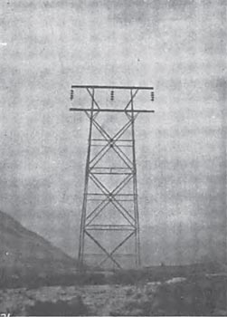
| |||
| Fig. 4. Suspension Insulators on 60000 Volt Transmission Line |
Various tests have been made from time to time to determine the amount of voltage across the several petticoats of a pin insulator and various suspension insulators, and results made by different people vary a great deal. The spark gap method at first seems attractive, but actual tests show that this method is very misleading and that the values obtained are not a true representation of actual conditions. With the spark gap, it is possible to reach a point where one gap will charge into the next, and that into a third, and so on. That is, the presence of the spark gap equalizes the potential; so that by manipulating the conditions, we can have either an equal or unequal distribution across a series of units.
As another instance: in testing a triple petticoat insulator, it is possible to puncture the inner shell by first wetting the first and third shells, thus causing the middle shell to take practically all the voltage. This shows us how complicated this matter may become, and why different engineers can obtain different results, simply by the surface of the insulator being oily and shedding water for a time.
The shunt resistance method seems to be accurate, and the readings that have been given above were made by this method and re-checked. When making tests by this method it is necessary to permit an actual current to flow, so that the potential drop across the insulator can be measured.
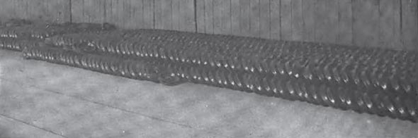
| |||
| Fig. 5. Suspension Insulators in Factory of General Electric Company, Schenectady, N. Y. |
The size of the testing transformer should also be considered; as it is possible with a small transformer to test an insulator under rain and have it appear to be satisfactory when this is not the case. This is because the current delivered by the transformer is so small that the film of water will carry it without steaming, assuming voltage to be held on low tension side, whereas a larger transformer would cause arcing. Results are sometimes misleading unless we consider the different transformers. In tests a point is reached where the static sparks begin to strike over the surface and being of an oscillatory nature they set up disturbances which give rise to voltages higher than that which is read on the low tension side of the transformer. In consequence of this, the insulator appears to be sparking over at a much lower voltage than is really being impressed. Some tests show this effect to a marked degree, and in a laboratory test this would indicate that the insulation was of a lower value than would show up under the actual working conditions. In view of the many sources of error that may arise in the testing of insulators, it is of first importance that this work be entrusted only to those who thoroughly understand it; who are not likely to be led astray by secondary phenomena, and who are supplied with suitable apparatus.
The porcelain used in the manufacture of insulators should be selected with the greatest care, as it must have a high insulating value and a thoroughly vitrified structure which resists the entrance of moisture; besides being free from any tendency to weaken or deteriorate in any way with age or severe service conditions.
Commercial tests on insulators, as a check on the product and manufacture, are quite essential, and should be gone into very carefully. It is a comparatively simple matter to make a dry test, but when rain tests are considered, we have to deal with a vague quantity. When some manufacturers speak of the "rain test" value of an insulator they mean that this insulator has a certain insulating value in a rain storm, the rain being supplied as the fancy of the engineer may dictate, some specifying a "cloud burst. " Even though we agree on a certain precipitation, the results may vary, as the distribution of the rain in one test may be quite different from that in another, owing to the different pressure, position of nozzles, velocity of wind, condition of insulator, and the specific resistance of the water change, due to the presence of impurities. When testing suspension insulators for a rain test, the rain should be angular and the insulators vertical. It has been proposed as a more convenient method to test insulators at an angle and let the rain drop vertically. This is not satisfactory, as it is not as severe as the old method, because when the insulators are vertical they are "bridged" by the rain running off the edges.
The dew test can be controlled with some degree of precision, but is rather difficult to make owing to the complications. A steam test has been proposed which consists essentially of training a jet of steam on the insulator, or housing the insulator in a steam pot and subjecting it to the electrical test. This gives uniform results, as the evaporated water is of the same resistance and is distributed evenly.
Insulators and metal fittings operating at high voltages on transmission lines are sometimes coated with a formation, probably due to ozone, which has the appearance of an oxide. By actual test a number of insulators operating at 100,000 volts in a cloud of steam have given no trace of nitric acid unless the voltage was increased to a point where there were disruptive discharges. From this it would seem that nitric acid is only produced when there is a disruptive discharge, and is not due to corona or glowing.
There has been some discussion as to the heating of porcelain due to dielectric hysterisis. Tests have demonstrated that there are very small internal losses in the body of the insulator if the porcelain is thoroughly vitrified, the porcelain is coarse, however, it will absorb moisture, which under electric stress will give a rise in temperature (perhaps I2 R loss) that is misleading. At the same time a poor porcelain will absorb moisture gradually giving the effect of deterioration. Three-quarters of an inch of porcelain will stand 85,000 volts commercially. Samples of porcelain taken from five different manufacturers show different percentages of absorption when the various samples were selected at different times. This indicates that even though extra precautions are taken to secure the best porcelain, there are times when porcelain that will absorb moisture is obtained in spite of specifications. From this it is easy to see that we should specify absorption tests on insulators from time to time, or even from every kiln, to be sure that the product is running uniform. "Pilot" insulators should be without glaze so as to obtain the most severe conditions; for it is possible with a good glaze to exclude moisture until that time has arrived when the glaze has become "crazed" or cracked. For this reason porcelain insulators should never rely for their insulation on the glaze; the whole body should be thoroughly vitrified.
Good porcelain will stand soaking in water, and even a very small per cent of absorption should be considered enough to condemn the insulator.
The insulators which are exposed to the elements gradually accumulate a film of dust which ordinarily will not affect the insulating value unless moisture is present. Insulators exposed in tunnels where there is a great deal of soot and dust, were afterwards tested electrically, and found to have very nearly the same insulation as originally, but under rain or dew test these arced over much below the test with a clean surface.
This type of insulator is not only used as a means of suspending transmission lines at high voltages, but at moderate voltages, it finds a wide field of application in the suspension of transmission lines across railroad rights of way and other points where the greatest mechanical safety and electrical protection is desired.
References:
Porcelain for Electrical Purposes, L. E. Barringer.
GENERAL ELECTRIC REVIEW, March, 1908. Insulators for High Voltage Transmission Lines, E. B. Merriam.
GENERAL ELECTRIC REVIEW, August, 1907. A New Type of Insulator for High Tension Transmission Lines, E. M. Hewlett.
Transactions of A.I.E.E., June, 1907. Some New Methods of High Tension Line Construction, H. W. Buck.
Transactions of A.I.E.E. June, 1907. The Testing of High Line Insulators, C. E. Skinner.
Transactions of A.I.E.E., June, 1908.
