[Trade Journal]
Publication: The Electrical Engineer
New York, NY, United States
vol. 8, no. 93, p. 388-394, col. 1-2
SPRAGUE SYSTEM FOR ELECTRIC RAILWAYS.
THE advance of electricity as applied to the propulsion of street cars has indeed been remarkable. About two years ago there were a few experimental electrical roads in operation, but street railway men, as a rule, especially those connected with large corporations, did not seriously contemplate the substitution of electricity for horses, or mules, or the cable, as a means of propulsion. About this time, however, a syndicate of capitalists secured the franchise for an electric street railroad in the City of Richmond, Va. The grades on the road were such that the use of horses as a motive power was impracticable. It was at first determined to put in a cable road; but as several of the electrical companies were at this time advertising their systems for propelling street cars by electricity, the question of using this new motive power was seriously considered, with the result that a contract for the electrical equipment of 12 miles of street and 40 cars was finally awarded to the Sprague Electric Railway and Motor Co.
It was certainly a great undertaking for a company which at that time had not a single electric road in operation to undertake the equipment of a road the size of that at Richmond. But the Sprague company rightly assumed that if this road, presenting as it did, all the difficulties to be met and overcome in street railroad practice, could be equipped and successfully operated, then all questions as to the feasibility of this new application of electricity would be met and its adoption would become general throughout the country. The past two years have amply proved the correctness of this assumption.
 |
| Fig. 1. Sprague Electric Railway System. Compound Wound Dynamo. |
In starting work on the Richmond road the Sprague company naturally had to follow ordinary street railroad practice as far as the road-bed, track and cars were concerned; but certain principles were determined upon in the electrical installation, which principles, embodying as they did then, and do now, the distinctive features of the Sprague system, may be briefly enumerated as follows:
1st. It was determined to place the motors entirely beneath the car. This was an entirely new departure and evoked at that time the ridicule, not only of street railway men, but also of many electricians.
2d. In order that the whole weight of the car might be available for traction two motors were used, each driving, independently, one axle.
3d. The motors were centered on the axle; direct gearing was used throughoutthere being no sprocket wheels and chains.
4th. In order to relieve the gearing, bearings and moving parts of the motor from the inevitable strains and jars to which they would be subjected in their novel position, the ends of the motors furthest from the axles were sustained in position by a yielding support.
5th. It was determined to control both motors from 3 single switch placed on either end of the car; the necessary variations in the speed of the motors to be obtained by varying the resistance of the field winding of the motors traversed by the current; thus using no external resistance whatever.
6th. It was determined to carry the supply current on a main conductor strung on poles at the side of the street and feeding at proper intervals into a smaller working conductor, placed over the centre of each track, against which the contact wheel should press. Owing to the great length of the line, four main feeders were run from the power station and tapped into the main current wire at four several points, to maintain the electrical pressure substantially constant. The return circuit was established through the rails and ground, the rails being connected together electrically by means of copper bands and reinforced by earth plates sunk into the ground at intervals along the line.
7th and last, it was decided to use an under-running contact wheel, supported on a suitable movable arm from the top of the car.
These principles were faithfully embodied in the Richmond road, and they are to-day the principles upon which all electric railways of any magnitude, using the overhead construction, are successfully operated. They are claimed to have been determined upon and enunciated by Mr. Sprague before one of them had been tested in practice and before the Sprague company had a single road in operation. The fact that every successful electric road in operation in the country to-day embodies some or all of these principles is the best practical proof that they were as sound then as they are now.
The Richmond road served to illustrate the success of electric traction on a large scale and under typical conditions of difficulty. To-day, as a result of its success the records show that more than 100 electric roads are either in operation or building, comprising about 400 miles of track and nearly 1,000 cars. The Richmond road demonstrated clearly that electric motors could carry heavily loaded cars up grades as high as 10 and 12 feet in a 100, at a speed of five or six miles an hour; that cars could be forced over tracks covered with mud and ice in winter; that they could be run at a speed of 15 to 20 miles an hour on the level ; that motors could be put under the cars within three or four inches of the ground and run in that position 18 or 20 hours a day, day after day, exposed to the influences of the weather and to the dust, dirt and mud of the streets; and last, but not least, that cars could be operated by electricity at a cost very materially less than that of horse or cable traction. These were the very facts which street railway men questioned, and they were facts that could only be successfully proved by actual demonstration on a sufficiently large scale. The deduction to be made from these facts is plain and simple, namely: that the electric motor will rapidly replace all other forms of motive power on street railway work.
The overhead system will undoubtedly be retained in smaller cities and towns and in the country, connecting towns, while the storage battery, which is rapidly assuming a practical and successful form for street railway work may be utilized in large cities where the overhead rights cannot be obtained, and where the grades do not exceed five or six feet in 100.
POWER STATION.
In describing the Sprague system one naturally starts at the power station where all the experience and best practice of large lighting stations are taken advantage of to produce the most economical results. In some places a water power can be taken advantage of to drive water wheels belted to the dynamos; but in the large majority of cases the steam engine must be resorted to as the prime mover. In the economy of a plant much depends upon the style of boilers, furnaces and engines used, and the Sprague company has given great attention to these details. In estimating on the power required at the engines, about 10 h. p. per car is usually allowed which gives an ample reserve capacity. Thus, in Richmond, where the grades are very heavy, the average electrical horse-power per car at the station varies from 4 to 6; in Scranton, where the grades are equally heavy, about 5; in Cleveland, where the road is level, but where tow cars are run and very heavy loads carried, 4 1/2; in Lafayette, Ind., where the duty is comparatively light, from 2 to 3. Owing to the variation in the load on the dynamos the Sprague company now use compound wound machines (dynamo, figure 1) entirely. Much attention is given to the regulation of the engine speed in order to maintain a constant electrical pressure at the station. The proper and uniform operation of the cars depends largely upon this important feature.
| |||
| Fig. 2. Sprague Electric Railway System. Power Station, Scranton, Pa. |
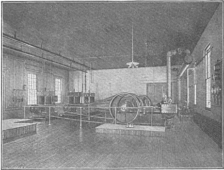
Figure 2 shows the interior of the Sprague station at Scranton, Pa., from which it will be seen that great care is given to all those minor electrical details and fittings which go to make up the finished central station of to-day, whether used for light or power purposes. All wires leading into the power station are protected by lightning arresters; and in addition choking coils are placed in circuit with all the feeders, their object being to deflect a discharge of lightning from a path to ground through the dynamos and force it to go through the lightning arrester and thence direct to the ground.
OVERHEAD CONSTRUCTION.
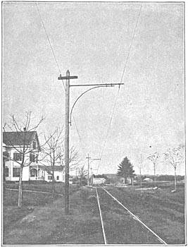
The distinctive characteristics aimed at in the Sprague overhead construction are efficiency, safety, lightness and neatness. Owing to the system of main feeders and main and working conductors, already mentioned, the electrical pressure can be maintained nearly constant on a line operating any number of cars, and up to a distance of about six miles from the station. The loss on the line varies from 5 to 10 per cent. In places where it is not desirable to carry the main current wire and main feeders on the side of the street overhead they can be readily buried in the ground, in suitable subways, leaving only one small wire over the centre of each trackthat wire being 1/4 inch in diameter.
In order that this working conductor may possess the necessary strength with its small dimensions, a silicon bronze wire of very high tensile strength and high conductivity is used. This enables the wire to be put up very taut, and at the same time leaves an ample factor of safety to withstand any unusual strain or weight that may be put upon it. In order that one section of the line may, if necessary, be cut out of circuit, as, for example, in case of a fire or accident on any portion of the line, sectional cutout boxes are placed at intervals along the lines on the poles. On long lines where two or more main feeders are used the cut-out boxes are placed in the main current wire; one main feeder supplying each section of the line with current, and the trolley wire being divided in sections by insulating breakers. If now an accident happens on any section of the line, a short circuit for example, the safety fuses in the nearest cut-out boxes are blown and this section of the line is cut out, all the rest of the road remaining intact. On short roads, where there is only one main feeder, the cut-out boxes are put into the auxiliary feeders, which connect the main conductor with the working conductor or trolley wire.
 |
| Fig. 3. - Sprague Electric Railway System. Trolley Wire Insulator Pull-Off Bracket for Curves Pole Ratchet Overhead Switch. |
Should a road increase the number of cars at any time in operation none of the line work is disturbed. It is necessary simply to put an additional main conductor on the side of the street, the size of the trolley wire remaining as before. This is an advantage where railroads equip portions of their roads with a view of increasing the equipment later. The use of a small wire over the centre of the street reduces strain on the supporting structure and permits the use of fewer poles, facilitating convenience in repairs. Where all the copper is put into the working conductor over the centre of the track a break at any one place in this wire stops all the cars beyond the break, and may necessitate the shutting down of the power station. In addition, if the number of cars on the road be increased beyond the original calculation this wire must be taken down and a larger one put in its place. With a line subdivided into sections, which can be made independent of each other at will, only one section of the line can be disabled at one time and the liability of loss of traffic due to accidents or the shutting down of the road is reduced to a minimum. Many of the detail parts of the overhead system have been the subject of careful study and thought.
The line insulators which support the working conductor or trolley wire; the pull-off brackets, which support the trolley wire around a curve; the pole ratchets, for taking up the slack in the span wires; the overhead switches, for directing the contact wheel on to the proper wire, where two or more wires cross or diverge; the insulating breakers in the working conductor; the line cut-out boxesall these details of construction have been carefully worked out and a long series of tests made to determine the most practicable and efficient designs and construction.
There is much opportunity for the display of taste and even beauty in an overhead line. Figure 4 shows the Sprague road in Atlantic City with a single line of iron poles between the tracks; the trolley wire being supported at the end of the cross-arms, held in position by ornamental brackets. Figure 5 shows the single pole line construction at Brockton, Mass., with side brackets on the poles; this construction is generally adopted on a single track road, where the track is on one side of a wide street. The double pole span wire construction is used where the track is in the centre of the street or where there are two tracks of a double track road so close together as to prohibit the use of a single line of poles between them.
CAR EQUIPMENT.
It is on this branch of the equipment that the Sprague company have spent the most time and study and where the improvements have been most marked. After a year's experience with the first motors used, the new Sprague motor, shown in figure 6, was designed, in which the fruits of experience with the earlier motors were embodied. The new motor, in its electrical and mechanical details of construction and in its efficiency has proved a distinct advance over its predecessors. Some of its essential features may be briefly enumerated as follows:
All similar parts on similar machines are interchangeable.
All bearings of the armature and intermediate shaft are removable from the outside and interchangeable; the armature bearings are self-centering. The armature can be removed by simply removing one of the side brackets which support it, without dismounting the machine. The intermediate shaft can be removed from either side of the machine without dismounting. The gears are all independently removable without dismounting. All keys are abolished and replaced by feathers, with locking rings and cotter pins. All bolts have locking washers on them. The field coils are independently removable and waterproof. There are three ratios of gearing used on the machine, so that the motor may be geared for high speed on a level road, or slower speeds on roads where heavy grades are encountered. The proportions and relations of the armature, field magnets and windings have been carefully adapted for the production of the highest output and efficiency with the least possible weight. The motor can be applied to an ordinary street car or to any of the special independent trucks recently devised by various car companies for use in connection with electric motors.
| |||
| Fig. 4. Sprague Electric Railway System. Single Iron Pole Line, Atlantic City, N. J. |
The method of mounting the motor on the car is peculiar to the Sprague system, and deserves special mention. One motor is detachably centred on each axle so as to allow a yielding motion about the axle in any direction. In order to remove all shocks and strains from moving parts, and in order, further, to give the motor a yielding movement so that it may adapt itself to any change of load or any change in position of the car body or the truck, the end of the motor further from the axle is suspended flexibly from a cross sill on the car body above, or supported flexibly from below on the cross frame of the truck. The best method of support is from a cross frame, carried by an equalizing bar on the axle boxes of an independent truck; this method gives the greatest freedom in the movement of the motor and allows it to accommodate itself most readily to any and all changes in the position or motion of the car body or truck. In addition, the flexible suspension enables a single motor in Atlantic City to start two heavily loaded open cars out of the middle of a curve so easily and smoothly that the motion of starting is scarcely noticeable by passengers; and this with no undue strain brought on any of the moving parts.
The Sprague company claim broad control by patents of the general method of flexible suspension, the importance of which is very obvious. They also claim a broad patent controlling the use of the main and working conductor.
The motors are controlled on the car by a single movement switch on either platform; there being no external resistance between the motors and switch. By moving the switch handle one-half a revolution in either direction, the speed of the car can be controlled from the merest crawl up to a speed of 15 or 20 miles an hour. In order to show how quickly a car could be stopped, the controlling switch was suddenly reversed on a car in Cleveland with the car running 15 miles an hour, when the car was brought to a stand-still in a little more than its length. Thorough control of the motors becomes an important feature in crowded streets or where a car is running at a high speed. Two lives have been saved in Richmond by instantly reversing the motors and bringing the car to a stand-still. On each car a cutout switch is provided, so that by the turning of a crank either or both motors can be independently cut out of circuit. In addition, each car has a safety fuse and lightning arrester; and the cars are brilliantly lighted at night by incandescent lights.
| |||
| Fig. 5. Sprague Electric Railway System. Bracket Trolley Wire Suspension, Brockton, Mass. |
The contact with the trolley wire is made by a small wheel running on the under-side of the wire and pressed against the wire by the mechanism of the support, the latter being carried on the car top. The trolley support is mounted over the centre of the car, the rod carrying the wheel having freedom of movement in any direction, controlled by suitable springs; these movements allow the contact wheel to cling to the wire, even although the latter may vary greatly in height or in its distance from the centre of the track. Thus, in Scranton, the contact wire passes under two railroad bridges with less than 12 inches clearance from the top of the car, the bridges being separated only 150 feet; while between the bridges the wire is raised to a height of 22 feet where it passes over a railroad crossing. The side movement of the rod enables the wheel to follow the wire even when the latter is three feet to one side of the centre of the track. When it is desired to run the car in the opposite direction, the wheel is simply released from the wire and then placed on it again with the rod trailing in the opposite direction. The contact wheel is so constructed that it is self-lubricating, and the wearing rim or surface, made of phospor-bronze, can readily be removed when worn out and a new rim substituted in a few minutes.
 |
| Fig. 6. Sprague Electric Railway System. Car Motor. |
 |
| Fig. 7. Sprague Electric Railway System. Car Truck With Motor. |
The records of some of the Sprague roads show a remarkable duty for the cars; thus, in Scranton, with 17 cars equipped, every one of these cars has been in use daily, the grades on the road running from 6 to 10 per cent, and the loads carried being very heavy. The cars make from 70 to 80 miles per day, being an increase of 40 per cent. over the mileage previously made by horses. In Richmond, where the grades are heavier and the curves sharper than on any road in existence, and where both extend over long distances, 40 cars are in operation on busy days, this being the greatest number of cars ever operated on any electric road from a single station. In Atlantic City all the cars, 16 in number, are in continuous operation daily, and the loads carried are enormous; the cars make from 90 to 100 miles per day, and the 16 cars, with 9 tow cars, have carried in one day over 40,000 passengers. In Cleveland, where the motor cars also tow other cars, the mileage made is very high; thus, in May last, 17 cars made, in 487 car days, 45,640 miles, being an average of 93 7/10 miles per car per day. The maximum daily run was 193 miles, and one car, for nine days, made an average of 143 miles per day. These figures show that results which railway companies can obtain by the adoption of electricity.
In addition to increased car mileage, the cost of operation is also materially reduced. A year ago Mr. Sprague, in an article describing the Richmond road, gave some very elaborate figures on the cost of operation by electricity, including the cost of operating the power station, repairs, oilers, inspectors, etc. (see ELECTRICAL ENGINEER, August, 1888). At that time some of the figures were necessarily estimated, since no road had then been in operation a sufficient length of time to furnish reliable data; since then, however, data from several of the roads in operation have proved the accuracy of Mr. Sprague's estimate, and have shown, to the satisfaction of the Sprague company, that the cost of operation by electricity is from 4 to 5 cents per car mile, varying slightly with the cost of coal, the number of cars operated, the character of the road, etc., the average being about 4 ½ cents per car mile.
This cost includes coal, oil, waste, depreciation and attendance at the power station, also water and taxes, oil, waste and brushes on the motors, repairs and depreciation; in fact, all operating expenses, including the depreciation on the line, excepting only the wages of motor men and conductors, and repairs on the road-bed. The corresponding cost of operation with horses may be taken to be from 7 to 10 cents per car mile, and with cables slightly less than those figures.
The adoption of electricity, then, on street railroads means to the railway companies increased car mileage and decreased operating expenses. To the public it means much faster, pleasanter and cleaner riding, with a corresponding increase in the distance which they can conveniently travel between their homes and their places of business.
Two years ago to-day the Sprague company had one little two car road, one mile long, in operation in St. Joseph, Mo.; to-day they report, either running or building, 60 roads, aggregating 200 miles of track and 400 cars; while the capacity of the Edison Machine Works, with its ample facilities for turning out electrical machinery of all kinds, is taxed to its utmost to keep pace with the demand for the new Sprague electric railway motors.
