[Trade Journal]
Publication: The Electrical Engineer
New York, NY, United States
vol. 10, no. 125, p. 351-352, col. 1-2
LIEUT. FISKE'S NEW RANGE FINDER.
THE importance of being able to determine the exact position and range of an object to be fired at, whether from a fort or war vessel, is too obvious to need further exemplification, and hence a ready means of determining this point is evidently of the utmost practical importance in gunnery. As our readers may be aware, Lieut. Bradley A. Fiske, U. S. Navy, has devoted considerable attention to this subject, and has designed a variety of forms of these instruments. His most recent work in this branch is a range finder which embodies a decidedly novel application of the Wheatstone bridge as a means of measuring the angles, and by means of which ranges or distances can be read directly from a scale.
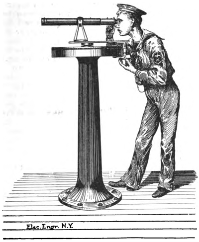 |
| Fig. 1. Lieut. Fiske's Range Finder in Position. |
Broadly considered, Lieut. Fiske's latest method consists in determining a fractional portion of a conductor bearing in length a ratio to the angle included between two lines of sight directed upon a distant object, and simultaneously causing a disturbance in an electrical balance, including the conductor in its circuit, proportional to the resistance of the fractional portion, and observing the difference in potential due to the disturbance.
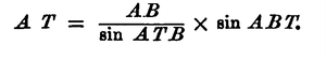
The accompanying diagram, Fig. 2, illustrates the simple and ingenious manner in which this is carried out. We will suppose AB to be a base line, and T the position of a distant object, the range of which AT is to be determined. By trigonometry, in the triangle ATB,
 |
Let C and D represent two telescopes pivoted at the points A and B and sweeping over arcs E and F of conducting material, the arcs having their extremities upon the base line AB. Let the telescope C be directed upon the point T1 assuming the position represented by C', in dotted lines. Then obviously, the angle C'AC is equal to the angle ATB and the portion of the arc E included between the positions C and C' of the telescope, will measure the angle at ATB.
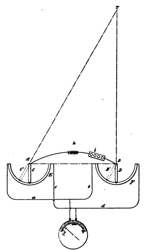 |
| Fig. 2. Method of Using the Fiske Range Finder. |
In the foregoing formula, the base line AB is known by measurement, and the angle ABT may be observed; and if the angle ABT, as shown in Fig. 2, a right angle, then the sin ABT becomes unity. It remains, therefore, to find the angle ATB in order to determine the distance AT; so that it becomes necessary to provide a simple and rapid means of at once determining what the angle ATB is. To this end, the conducting arcs E, F, are connected in the manner of a Wheatstone bridge, the four members of which are shown respectively at a, b, c, d. In this bridge is connected a galvanometer in the usual way, and also the battery h; the terminals of the battery wire being connected to the telescopes at their pivot points A, B, so that the circuit proceeds through the telescopes to the arcs, and then at the arc divides through the wires b, d, and at the arc divides through the wires a, c.
It will be plain that when the two telescopes C and D stand at right angles to the base line, and hence parallel to each other, the bridge will balance, and the galvanometer will show no deflection. The lines of sight of the two telescopes then being parallel, the galvanometer will then indicate infinite range; and of course, this will be true no matter where the telescopes may be on their respective arcs, so long as their lines of sight are relatively parallel. But if one telescope be moved out of parallelism with the other, as for example, the telescope G moved to the position C', then clearly the bridge will be thrown out of balance, and the galvanometer will be deflected. It will also be clear that the extent of deflection of the galvanometer will depend upon the length of arc included between the two positions of the telescope, C, C', and will be greater as that arc increases; so that with a battery of constant electromotive force, it becomes possible to determine the extent of movement of the telescope C by simply observing the indication of the galvanometer.
It will of course be obvious, that as the angle between the positions C and C' of the telescope increases, the length of the line AT will constantly decrease, while the deflection of the galvanometer will constantly increase; so that the galvanometer indicates ranges starting from infinity when the galvanometer shows no deflection, small ranges being indicated by large deflections of the galvanometer, and vice versa. As a matter of convenience, Lieut. Fiske employs for this purpose a galvanometer so constructed that the deflections of the index will be proportional to the differences of potential at the terminals.
It will be clear that by the method just described the operation of finding the range is reduced to a very easy and rapid process, and at the same time, greatly simplified as regards apparatus.
Observers stationed at the two telescopes C and D align them with the distant object, when a third observer instantly reads the range from the galvanometer, which is provided with a scale suitably marked in linear units, such as yards.
If, however, the angle ABT is not a right angle, then the factor, sin ABT, must be taken into consideration in solving the formula,
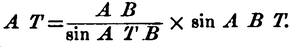 |
Or, in other words, the observer at the galvanometer may simply multiply the range indication by the sin ABT numerically expressed, in order to reduce the indicated range to the true range. The angle, ABT, is observed directly on the arc F.
In the foregoing demonstration, it is assumed that the resistance in the circuit remains constant, that is, remains the same as it is when the two telescopes are parallel to each other, and stand in the positions, CD, touching the middle parts of their arcs. But, as a matter of fact, this resistance does not remain the same when the telescopes move to positions nearer the extremities of the arcs. To illustrate, if the resistance of the circuit is a certain amount with the telescopes in the position CD, it will be less when the telescopes are turned in the position, C'D'. Now, the variation of resistance due to this change of position will affect the total resistance in circuit to an extent depending upon its ratio to the resistance of the whole circuit. And, consequently, if that ratio be made very small, as it easily may be by simply introducing a high resistance in the battery loop at i between the points A and B, then, inasmuch as the variation in resistance due to change in position of the telescopes may thus be rendered inappreciable, the total resistance of the circuit may be taken as constant; so that, despite the fact that the angle, ABT, differs from a right angle, the deflection of the galvanometer, as before, will remain practically constant for any given angle, ATB.
It is evident that if the high resistance before mentioned be not put in the battery loop, then the decrease in resistance due to change in position of the telescopes from the middle point of their ares toward the extremities of the arcs may bear a considerable ratio to the resistance of the whole circuit. And as this decrease in resistance will be attended by corresponding increase in current strength, it follows that proportionately greater deflections of the galvanometer will follow for any given angle, ATB; so that, consequently, the ranges indicated by the galvanometer will be less than those which would have been shown had the high resistance been put in the battery loop. Again, if the resistance of the battery loop between A and B is extremely small with relation to the rest of the circuit, the decreasing resistance of the whole circuit, due to change in position of the telescopes, may become very large; and this result may be intensified if the members a, b, c, d, connecting the arcs, are connected to those arcs at points less than 90 degrees from the middle points of those arcs. If, for instance, these wires were connected to the arcs at points 81 degrees removed from the middle points, and if the resistance in the battery loop were one-tenth of the arc of 81 degrees, then when both telescopes were moved to positions 60 degrees from the middle points, the resistance of the whole circuit would then be only about half of what it was when the telescopes were at the middle parts or the positions CD. Consequently, for any given relative angular displacement of the telescopes occurring 60 degrees away from the middle points of the arcs, the corresponding deflection of the galvanometer would be about twioe as great as if the same relative angular displacement occurred when the telescopes were near the middle points of the arc; so that the range indicated in the latter case would be about half as great as in the former.
But it will be observed that if the telescope, D, for instance, were 60 degrees removed from the central position, the angle ABT would be 30 degrees, or 150 degrees, and then its sine would be one-half; so that the range indication for any given angle ATB, would be only onehalf of what it would be with the same angle ATB when the telescope at D' is in its middle position. In other words, the fact of the decreased resistance caused in the circuit as the telescopes move away from the middle position, tends to automatically make the very correction for the sine of ~ABT~~ which ought to be introduced, because the telescope no longer stands at 90 degrees to the base line; and this is found to be the actual occurrence in practice.
In what has been said above, the resistance of the galvanometer has been neglected, and it has been assumed that the E. M. F. and internal resistance of the battery, and the resistance of the various contacts, remain constant. While this is not theoretically true, Lieut. Fiske finds that by using storage batteries and by making the contacts carefully, no appreciable error is introduced. Careful experiments with this range finder at sea, show that the errors of the instrument are insignificant and the indications absolutely instantaneous.
Fig. 1 shows the range finder as actually used on shipboard. The instruments are made of aluminum, bronze and iron, and are left exposed on deck without any protection whatever, except that a cover is placed over the telescope when not in use. The instruments require no care except an occasional cleaning.
