[Trade Journal]
Publication: The Electrical Engineer
New York, NY, United States
vol. 10, no. 128, p. 409-417, col. 1-2
THE RAE ELECTRIC RAILWAY SYSTEM.
As our readers may be aware, one of the first electric railways put into operation was the Highland Park Electric Railway, which was started in 1884, and is still in successful operation. This road was built by the Detroit Electrical Works, who some time ago put their railway and motor department in charge of Mr. Frank B. Rae, as electrical engineer, who has developed the system so that it represents to-day a whole, complete in every detail. As a complete description of the Rae system has not yet appeared, we present such an one to readers, from which it will be evident that Mr. Rea has struck out on a new line in more than one direction.
| |||
| Fig. 1. the Rae Railway Power Generator. |
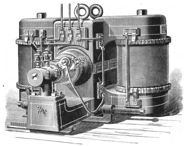
Beginning with the main source of power, the electric generator, we would call attention to a number of novel features entering into the construction of the Rae railway power generator. This machine, which is illustrated in the accompanying engraving, Fig. 1, is built in sizes of 40,000, 65,000, and 80,000 watts. The standard E. M. F. of 550 volts is maintained throughout the Rae system, and in order to avoid variation in potential on the line, with its consequent ill effects, the generators are compound wound. The field magnets, in order to obtain the highest magnetic effects, are made with wrought iron cores, and so that the magnetic strength may remain equal throughout the circuit, the cast iron employed for the yoke pieces is made of a section equivalent in magnetic capacity to that of the wrought iron.
Experiment has shown that the influence of the compound winding is enhanced by placing that winding as close to the armature as practicable. This has been carried out in the present instance by placing the winding on the cast iron yokes at the end of the cores. The compound winding, it will be noticed, consists of a flat ribbon of copper, which is made equal in section to that of the armature conductors.
The Siemens armature, which is employed, is encircled by pole pieces, which are made equal in length to that of the armature by being extended at right angles to the main yoke pieces. The armature is built up of soft iron discs .007 inch in diameter, covered with shellaced tissue paper, and at every 20 discs a layer of shellaced cloth is interposed in order to thoroughly provide against the generation of Foucault currents. These discs are mounted on four brass splines, let into the shaft, and so arranged that an air space is left between the shaft and the inner diameter of the discs. By this construction it will be seen that no magnetic lines pass into the shaft, being prevented from doing so by the intervening air space; and thus practically entirely avoiding leakage and straying of lines from the shaft and bearings. The commutators of all the machines have 80 sections, and the following are the electrical dimensions of the 65,000 watt machine: Armature wire, 1,000 feet of No. 4 B. & S., resistance, .061 ohm. Shunt winding, No. 17 B. & S., resistance, 250 ohms. The series coil, as above stated, has a carrying capacity equivalent to that of the armature, and consists of 60 turns complete, 15 in each coil.
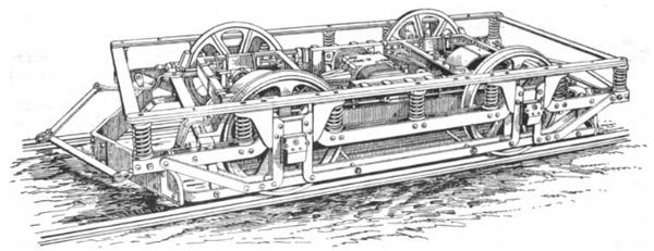 |
| Fig. 2. Single Motor Truck, Rae Electric Railway System. |
Particular care has been taken with the connections of the machine, which are all permanently made before being sent from the works. These connections are all composed of copper bars, corded and covered with insulating paint, which is afterwards polished to resemble hard rubber. The shafts and bearings of the machine are extra heavy to withstand the sudden strains which are frequently experienced in railway work.
We come now to what is probably the most important element of an electric railway system, and that is, the motor and truck upon which it is mounted. Much has been said and written in the past on the method of gearing employed, and the relative advantages and disadvantages of each. In accordance with the tendency which seems to be gaining ground in more than one quarter among electric railway engineers, Mr. Rae employs but a single motor on his car, gearing it to both axles. The reduction of the source of power to a single machine brings with it advantages which cannot be denied; involving, as it does, the equal distribution of power, irrespective of the load on the axles, and reduction in the number of gears and frictional surfaces, and the possibility of employing larger diameters of gears and pinions, with larger wearing surfaces. The general design of the Rae truck is shown in the accompanying engraving, Fig. 2, and Fig. 3 shows the same in plan. The motor has fields and poles of solid wrought iron forged, with the end yokes only of cast iron. From the sides of the pole pieces extend brass arms, which support the armature. A pinion at one end of the armature shaft gears directly with the gear of a counter shaft, which transmits the motion to both main axles by a bevel gear at each end. By this arrangement the speed of the motor does not exceed 900 revolutions at the full speed of the car.
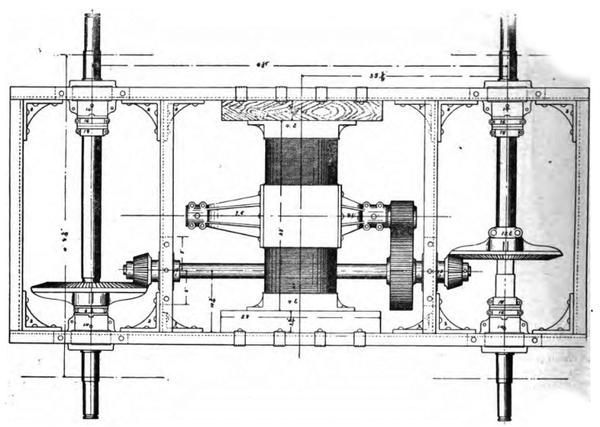 |
| Fig. 3. Plan View of Truck, Rae Electric Railway System. |
The frame on which the motor and gears are mounted is made of channel iron bars with carefully leveled joints, planed square and true, put together with hot rivets, and finally tested for spring. The frame is absolutely rigid, in contradistinction to the usual practice of flexible construction of the motor support. To that end the axles are mounted in rigid bearings and side motion prevented by the use of graphite friction collars, which can be taken up when they wear. This avoids all back lash of the gear and consequent noise. The bevel gears are thoroughly encased in dust-proof boxes and run in oil. The motor is entirely insulated, being supported at the sides, as shown, by 2 1/2 inch oak pieces saturated in asphalt, and in addition by the raw hide or leatheroid pinions employed. The motor is of 30 h. p., and in the 16-foot car type a 6-foot wheel base is employed.
Special attention has been paid by Mr. Rae to the question of lubrication, and for that purpose all the bearings are bushed with graphite, doing away, practically, with oil, and thus avoiding the dirt and other inconviences [sic] inconveniences attendant on its use.
| |||
| Fig. 4. Switch-Handle on Platform. |
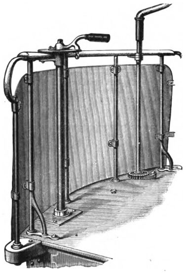
The motor employed on the car is series wound, and the means employed for its regulation by the motorman on the platform are exceedingly simple. The arrangement for that purpose is shown in the accompanying engraving, Fig. 4. The regulation of speed is effected by the interposition of four resistances through the medium of a very simple switch. These resistances are successively connected with the circuit in parallel, and finally short-circuited. The switch and rheostat containing these resistances is placed under the car, entirely out of the way, and on the platform of the car the single handle illustrated in Fig. 4 is placed. This is moved in one direction, or the other, for going ahead, or reversing. At the centre point a stop is provided, shown below the plate, to prevent accidental reversal of the motor by the motorman throwing the switch handle over beyond the middle point. By pulling out the stop, however, the handle can be reversed. The space occupied on the platform by this arrangement is very small and does not interfere with the occupancy of the platform by passengers.
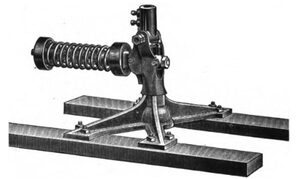
A number of other details of this system relating to the overhead construction will also interest our readers. Among these are the trolley and trolley stand. These are illustrated in the engravings, Figs. 5 and 6. The trolley wheel, it will be noticed, is mounted upon a tubular steel pole, made in one piece, and drawn to three reductions, being inch in diameter at the top and one inch at the bottom. This makes an exceedingly light and strong pole, and thus avoids considerable strain on the trolley stand mounted on the top of the car. The stand, shown in Fig. 6, is of special construction, and so designed that the tension on the springs is equalized throughout the range of motion of the pole. This is accomplished by an arrangement which changes the leverage between the spring and the stub end of the pole.
| |||
| Fig. 5. Trolley Wheel and Pole. |
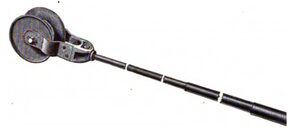
The trolley wheel itself, mounted on the top of the pole, has a bearing centre of phosphor bronze, the flanged sides which maintain the wheel in contact with the wire being of steel. In order to avoid oiling of the trolley wheel, graphite bearings are employed; the metal of the pole is also used as a conductor leading from the line wire to the motor.
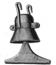
Mr. Rae has also designed a special trolley line hanger and insulator. This consists of a bell-shaped, porcelain or lava insulator, Fig. 7, with a groove in its head, in which is inserted a brass clamp provided with yokes. A brass bolt is let through the insulator and secured by a nut at the top. This nut fits into a square socket, which is then filled up with insulating material. The clamp to which the line wire is attached is swiveled so as to give full play to the wire. These clamps are of brass. After being hooked on to the span wires the hooks are closed at the lower ends, which firmly secures the insulator in position.
| |||
| Fig. 6. Trolley Stand on Top of Car. |
In all Mr. Rae's overhead work the use of solder for connecting the various parts has been entirely avoided, as experience has shown that the heat required to sweat the parts together softens the copper, and when, later on, the slack is taken up, the copper draws at the point where the heat has been applied. To avoid this, therefore, screw clamps are employed throughout. Thus, as just pointed out in the case of the insulator, the wire is clamped to the swiveled suspension and the lower edges of the clamps brought down to a knife edge, so that the trolley passes under the insulator smoothly and without jumping.
| |||
| Fig. 7. Trolley Line Hanger and Insulator. |
This idea has also been carried out in the strain plates employed. These plates are put in at distances of about 1,000 feet, to take the strain off the line, and are also employed at curves, being so arranged as to pull the trolley wire towards the curve and thus to relieve the poles at the curve of all strain. The pull-off used by Mr. Rae embodies this same clamp feature. It is made of a wooden spindle saturated in paraffin and having brass ferrules at each end. The goose neck is made of steel and the whole is painted with insulating paint.
| |||
| Fig. 8. Rae Horn Ammeter. |
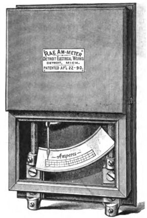
Among the various station details employed in connection with the Rae system, space permits our drawing attention to only two; these are, the ammeter and the main switch. The former, which is shown in the engraving, Fig. 8, is what is known as the Rae horn ammeter, taking its name from the shape of the iron core employed. The divisions are practically equidistant over the full range of the scale.
The compound station switch has three pairs of contacts so arranged that the attendant, of necessity, closes the proper contacts at the proper time, and, vice versa, opens them in their proper order. Thus, the uppermost of the three switches is connected to the trolley wire bus, the central one to the neutral bus and the lower to the ground, in this way the proper connections and disconnections are made automatically.
| |||
| Fig. 9. Saginaw Union Street Railway, Rae System. |
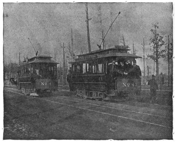
These constitute the main features of the Rae system, which is now in successful operation in various cities among them Detroit, Mich., Elkhart, Ind., Fort Worth, Tex., Saginaw, Mich., and other places. The accompanying illustration, Fig. 9, shows a view of one of these roads. It has been remarked that the ease of riding and freedom from noise in the operation of these cars are noteworthy, and the employment of a single motor in place of the customary two is also a feature which the operators of electric railways will appreciate.
