[Trade Journal]
Publication: The Electrical Engineer
New York, NY, United States
vol. 10, no. 132, p. 527-529, col. 1-2
LIEUT. FISKE'S POSITION FINDER.
IN a recent issue¹ we described the valuable range finder of Lieut. Bradley A. Fiske, by which a gunner is enabled to know accurately the distance of the object which he is firing at. This instrument can be applied in many situations on land and on board ship, butpresupposes, of course, that the gunner is able to sight directly upon his target. In modern fortifications, however, the tendency to the employment of what are known as disappearing carriages is becoming stronger every day and hundreds of such carriages are already employed in sea coast forts abroad.
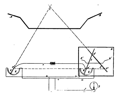 |
| Fig. 1 Diagram of Fiske Position Finder. |
In these forts the guns are loaded below the level of the parapet and when ready to fire are raised into firing position, usually by a hydraulic ram. This method of operation evidently protects those charged with the loading of the gun while the operation of loading is in progress; but it is evident, that by the means heretofore at hand, it has been impossible to sight the gun while depressed behind the parapet. True, the range could be determined beforehand by means of the range finder so as to permit the gun to be given the correct elevation before raising to fire, but this gives no indication of the true direction of the object to the concealed gunners, and hence deprives them of an essential factor in the pointing of the gun.
What was wanted, therefore, was some means by which the gunner could obtain both the range and direction of the object, with regard to the gun as a central point, in other words, their relative position. It is this which Lieut. Fiske has now accomplished, and in virtue of which the gunner is enabled to locate on a chart, drawn to scale, the exact position of a distant object which he has no means of seeing, but which is being sighted on by two observers placed at any distance, well protected from the fire of the enemy and unobscured by smoke.
The new position finder may be said to be a simplification and amplification of the range finder. It embodies, first, a telescope moving over an arc of conducting material and which is directed upon the distant object; second, a pivoted pointer moving over a like arc of conducting material in a Wheatstone bridge circuit with the first-named arc; the arrangement being such that when the alidade arm attached to the telescope on the first arc, and the pointer on the second arc stand at the same angle, the circuit is balanced. The pointer arm moves over a chart representing the area which includes the position of the distant object on a reduced scale. On this chart there is a simple pivoted arm which can be trained directly upon the object; or the arm may be mechanically controlled by a telescope directed upon the object so that it will make with the other arm an angle equal to that made by the lines of sight drawn from the two telescopes to the object. The position of the object is then shown by the intersection of the electrically directed pointer and the mechanically directed arm upon the chart.
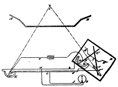
In the accompanying illustrations, Fig. 1 is a diagram showing the general arrangement, and Fig. 4 is a similar diagram showing the chart D in different position, AB represents, for example, the parapet of a fortification. The distant object is supposed to be located at C; and it is the position of this object which is to be determined upon a chart D, on which the fortification line A'B' appears on a reduced scale, E is an arc of conducting material and F a telescope or arm pivoted at one end at F' with its free extremity moving over, and making contact with, the arc E. G is an arc similar in all respects to the arc E and located in proximity to the chart D. H is an arm pivoted at H' and having its free end sweeping over, and making contact with, the arc G and carrying a pointer I. a, b, c, d, are members of a Wheatstone bridge connecting the arcs E and G. E is a loop including the battery, and f the loop including the galvanometer g.
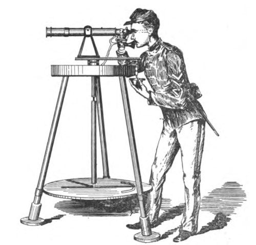 |
| Fig. 2 Fiske Position Finder in Use. |
Now it will be obvious that when the arm H is set upon its arc G at the same angle to the line H'F' as the arm F upon the arc E, then the bridge will balance and the galvanometer will indicate zero; and hence, inasmuch as the telescope F points to the actual object C, so the arm H will point to the corresponding position of the object C or C' on the chart D. Pivoted upon the chart D at J' is an arm J, which arm may be provided with a telescope or alidade, so that it may be directed upon the object c, the arm J being long enough to make intersection with the arm i.
If then the arm J is trained directly upon the object, inasmuch as the line H'J' joining the pivots of the arms IJ on the chart D corresponds to the base line F'J'' extending between the distant stations, and as the angle C'H'J' equals the angle CF'J', it follows that the intersection of the arms I and J at C' indicates the position of the object C upon the chart D. The chart being drawn to scale and laid off in divisions of known dimensions, it then becomes easy to recognize at a glance both the bearing and distance of the object c from any given point on the chart.
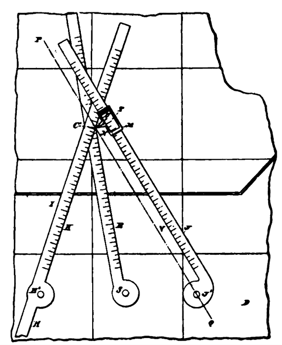 |
| Fig. 3 Interesting Pointers, Fiske Position Finder. |
In actual practice Lieut. Fiske has adopted the form of apparatus represented in Fig. 2. This consists of a tripod supporting an upper platform which carries the standard upon which is pivoted the telescope. Extending downward through the platform is a shaft which turns with the telescope and standard. An arm is carried by the shaft and moves over a lower table on the upper surface of which is marked the chart. The arm is set parallel to the telescope; so that when the telescope is directed upon the object, the arm will also be directed upon the object. This parallelism of arm and telescope, however, is not essential. Carried upon the lower table is another arc and a second arm. The intersection of the two arms over the chart, as already explained, shows the position of the distant object; and the apparatus of Fig. 2, as indicated in Fig. 1, is located at one station, while the arc E with its telescope F is located at another distant station.
Referring now to Fig. 4, it will be seen that in this case the line H'J' on the chart D, while corresponding, as before, to the base line F'J', does not coincide with that line, and hence that the arm J is itself not directed upon the object. This represents the condition before referred to when the arm J is not set parallel to the axis of the telescope M, but at an angle thereto ; this angle being such that the angle H'C'J' will continue the same as the angle F'CJ' despite a change in relative position of the chart D; such as indicated in Fig. 4.
In Fig. 3 is represented a construction of the intersecting arms I and J, which is especially adapted for the uses before detailed, and which allows of the actual intersecting point being determined with great accuracy. It will be obvious that with a chart laid out on a small scale and using arms IJ of sufficient width or thickness to give them rigidity, the exact point of intersection of lines drawn through the pivot centres of the arms will be difficult to determine; and there may be considerable error in regarding the apex of any one of the four angles made by the intersecting arms as the true point indicated. In the device shown in Fig. 3, this source of error is practically eliminated; and in addition other advantages are secured.
The arm I has one edge K on a line passing through the pivot centre H'. On the arm J is a slide M, which carries a pointer N, projecting from the edge V; the extremity of this pointer being upon an imaginary line drawn through the pivot centre J' and indicated by the dotted line PQ. It will be obvious that the point on the arm I indicated by the pointer N, will be the exact point of intersection of lines drawn through the pivot points H'J'. The arms I, J are graduated lineally to conform to the scale of the chart D; so that the distance of the object from both separated stations can at once be read. Thus, on the rod I may be read the distance HC' which is that of the object from the station at which is located the telescope F, Fig. 1 ; and on the rod J may be read the distance J'C', which is the distance of the object from the station at which is located the chart D. If it be desired to determine the distance of the object from any intermediate station between the two mentioned, a third pointer E may be placed in position between the two arms IJ, and situated in the same relation thereto as the intermediate station is to the two extreme stations. The distance from the pivot point S of this arm to the point C', the place of intersection of the edge of the arm with the point of contact of the edge K of arm I, and the apex of the pointer N, shows the distance of the object from the pivot point S, and hence from the intermediate station. The slide M is moved along by hand. It is provided with an opening T, through which the scale marks on the arm J may be read, and to allow this reading being made, there is a central-mark U made on the pointer N which comes into coincidence with any one of the scale marks.
 |
| Fig. 4 Diagram of Fiske Position Finder. |
Telephones are fitted to the telescopes in the same way as in Lieut. Fiske's range finder. This arrangement of telephone and telescope overcomes one great difficulty always found heretofore with observers widely distant from each other; that is, the difficulty of maintaining both lines of sight on the same point. This difficulty, when the target is partially covered with smoke, as in the case of a war-ship firing her guns, has been considered almost insurmountable, since the smoke would cover, at times, the very part of the ship at which the telescopes were directed. The telephones, however, enable two observers to agree instantly upon what point to direct their telescopes, and enable them to change the point as often as the circumstances of the battle require. The instruments are constructed of aluminum, bronze and iron, and require no care except an occasional cleaning.
Lieut. Fiske's position finder at Fort Hamilton, New York Harbor, has now been exposed to the elements for two months without any covering or protection of any kind. At a recent trial, the average error in determining the positions of objects distant between a mile and a quarter and three miles, was about one-third of one per cent.
1. THE ELECTRICAL ENGINEER, Oct. 1, 1890.
