[Trade Journal]
Publication: The Electrical Engineer
New York, NY, United States
vol. 11, no. 153, p. 409-410, col. 1-2
EXPERIMENTS ON THE TRANSMISSION OF POWER AT VERY HIGH POTENTIALS.
PROBABLY the most notable feature of the Electrical Exhibition at Munich in 1882, was the demonstration by Deprez, of the practicability of transmitting power electrically over long distances. For this purpose, it will be remembered, Marcel Deprez employed two machines, one acting as a generator at Miesbach, and a second as a motor in the exhibition building at Munich, 37 miles distant, the current being sent over an iron telegraph wire 4 ½ mm. in diameter. The difference of potential at the generator was 1,343 volts and that at the motor 850 volts, while the actual work at the motor measured only 1/4 h. p.
As a demonstration of the improvements introduced since that time no better example could be afforded than the high tension transmission which it is proposed to show in connection with the Frankfort, Germany, electrical exhibition to be held during the present year.
 |
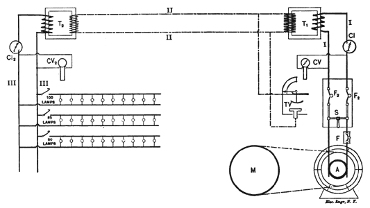
| Fig. 1. — Electric Power Transmission at 30,000 Volts Potential. |
The plan contemplates the transmission of 300 h. p. of the water power of the River Neckar, at Lauffen, to Frankfort, a distance of nearly 115 miles, by means of a copper wire 4 mm. in diameter. To accomplish this without very heavy loss in the conductors will evidently necessitate the employment of very high potentials, and in order to obtain data for the proposed work, a test installation was recently made at the works of the Oerlikon Company, near Zurich, who, in connection with the Allgemeine Elektricitatsgesellschaft, of Berlin, will undertake the transmission referred to.
Unlike the Deprez experiments, the present will be carried out by the aid of the alternate current transformer. The arrangement of the apparatus in the preliminary test is shown in the accompanying diagram, Fig. 1, in which I represents the generating station, n the line, and m the receiving station. As will be seen, an alternator A. was directly driven from the motor by belting, and by changing the speed, the potential could be varied from 40 up to 100 volts. The alternator generated a heavy current at a low voltage. For the proposed installation at Lauffen, the voltage will be 50 volts and the current 4,000 amperes. In this respect the system differs materially from the ordinary alternating current transformer systems. According to the opinion of the Oerlikon firm, the employment of wires of large size, with consequent decrease in the number of coils, will allow of a cheap construction of the dynamo, and afford much greater safety of operation. Quite apart from other advantages, the low voltage of the alternator removes the factor of danger for the attendants during the operation. From the alternator, the low potential current is carried to the transformer T1. On the way it passes through a single pole fuse F, through a double-pole single-throw switches, and double-pole fuse F2. In case of a fault in the insulation arising from too heavy load, or of a short circuit, the current would increase so much that the fuse, of the Cockburn type, will be blown; the weight of the leaden ball, suspended from the leaden fuse wire, tears apart both ends of the same, so that the circuit cannot be closed again by the two ends of the fuse melting together. The current is measured in the primary circuit by the current indicator C I, and its potential by the Cardew voltmeter C V.
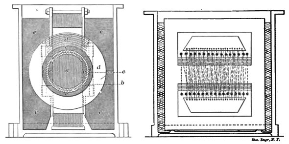
The transformer T1, designed by Mr. C. E. L. Brown, of the Oerlikon Works, is shown in two views in Figs. 2 and 3, It consists of a rectangular laminated iron core, on which both the primary and the secondary windings are placed, insulated from each other. The magnetic circuit is closed by two U-shaped iron pieces.
 |
| Fig. 2. and 3. — Transformer for 30,000 Volts Potential. |
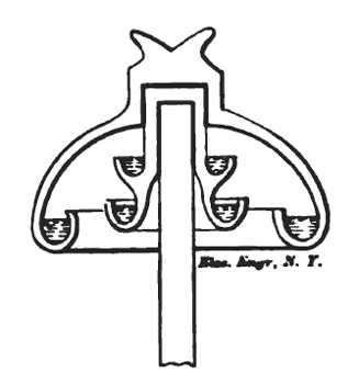
Experiments have proven that for such high potentials, hard rubber a few millimetres thick is only a safe insulator as long as it is absolutely homogeneous; as soon, however, as it gets a crack, the air which enters allows discharges of electricity to take place. Some kinds of oil have proven to be as good insulators as hard rubber. In order to prevent a discharge in the transformer, the latter is placed in a vessel filled with oil, the latter thus filling out all interstices and expelling the air which endangers the insulation. According to Mr. Brown's information, these transformers have proved to be quite safe, even at a potential of 50,000 volts. The transformer has a ratio of one to three hundred. The primary potential of the alternator of 40, 50, 65, 100 and 110 volts used for the experiments, thus produced a potential of 10,000, 15,000, 20,000, 30,000, 33,000 volts, respectively, in the secondary circuits. In the experiments, the line consisted of 7 kilometres of bare copper wire, 4 mm. in diameter, mounted in four parallel rows on the same supports by means of Johnson & Phillips oil insulators. The type of insulator proposed for the actual line from Lauffen to Frankfort is shown in Fig. 4.
 |
| Fig. 4. — Oil Insulator. |
The insulation of the line was tested by means of artificial rain, produced by the spraying of water from a hose. A Canlew voltmeter connected with the high potential secondary conductor indicating up to 100 volts, was connected to earth, and did not show any deviation. During a snow storm which took place, the same line did not show any leakage. The number of insulators used for this test amounted to 120. The Oerlikon works made use of spans of 80 to 100 metres, with copper wire of 4 mm. diameter. The oil insulators employed thus represented the insulating resistance of a line 10 to 12 kilometres long.
In the secondary circuit, the potential was measured by means of a Sir William Thomson voltmeter TV, which can be used for measuring potentials as high as 50,000 volts. A comparison made between the indications of this instrument and those of the Cardew voltmeters cv gave very satisfactory results. The secondary circuit is connected with a transformer T2. Its ratio of conversion is also from 1 to 300, so that it reduces the voltage on that of the primary conductors equal to that of the alternator. This transformer is also placed in a vessel filled with oil. The tertiary circuit at the receiving station had connected with it the current indicator CI, a Cardew voltmeter CV, and three series of 10 incandescent lamps run in multiple for 50, 65 and 100 volts, which could be switched on or off by the switches ss.
Special interest was excited by the experiments in the working of the fuses, and the induction in a telephone wire running parallel close to the power transmission line. The fuses were tested by making a direct short circuit, as well as by making use of the discharge current. They were inserted in the primary circuit because the small current used in the secondary circuit would necessitate the use of too fine wire. As soon as the secondary circuit was short circuited by means of a copper wire, the fuse was instantly blown. The short circuit was made by dropping a bare copper wire on the two secondary conductors. As is known, the blowing out of the fuses is accompanied by a small explosion; it was impossible to notice the smallest difference of time between the noise of the short circuit in the secondary wire and the explosion of the fuse. The extraordinary quick working of the fuse was proved by the fact that neither the secondary wires nor the copper wire used to produce a short circuit showed any traces of burning, notwithstanding the fact that the numerous short circuits which were made caused the copper wire and the conductors always to touch each other at the same place. In order to produce a discharge, two pieces of wire were connected with the secondary conductors, placed 22 millmetres apart. As soon as the secondary potential attained about 18,000 volts, the first discharges, accompanied by a dim light took place. At a higher voltage an arc was produced, causing at the same time interruption of the current by the blowing of the fuse.
In order to investigate the effect of the secondary current on telephone circuits, a telephone loop was run on the same poles carrying the secondary wires. It must be remarked that the secondary wires were arranged in four parallel rows, in order to enable the large amount of wire to be stretched within the limited space available for it. The speaking through the telephone did not meet with any difficulties, although their was a small noise caused by induction. The experiments, which have been of a qualitative character, proved that the transmission of power installation between Lauffen and Frankfort will not only be possible, but also absolutely safe. The working of the fuses evidently proved that short circuits which might happen by the falling or bending over of poles, will cause an instantaneous interruption of the whole plant. In the some way the installation, tested under very unfavorable circumstances, proved to be highly satisfactory.
