[Trade Journal]
Publication: The Electrical Engineer
New York, NY, United States
vol. 12, no. 181, p. 443, 458-459, col. 2, 1
THE CENTRAL POWER STATION OF THE WEST END STREET RAILWAY COMPANY, OF BOSTON
·
·
XVIII. — DETAILS OF LINE CONSTRUCTION.
·
·
While not strictly within the province of this article, the outside construction for the complete equipment of an electric railway system forms so important a feature that it is expedient to give some idea of the details, together with a few particulars of the track and the cars. At present there are about thirty-five feeders, varying in size from 200,000 to 500,000 circular mils, and amounting in all to about 180 miles of circuit. Some of these feeders run without being tapped direct to centres of distribution, frequently located in the car stations, from which the subfeeders can be controlled. Other feeders are tapped all the way along, making connection with the trolley wire at frequent intervals.
 |
 |
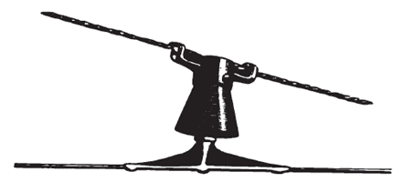
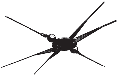
| Figs. 24, 26 and 27. — Details of West End Line Construction. |
 |
 |
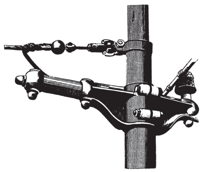
| Figs. 25 and 28. — Details of West End Line Construction. |
The poles for supporting the span wires and also the feeders are all of the Walworth type, manufactured by the Walworth Manufacturing Company, of Boston. These poles support the span wire, consisting of three No. 9 twisted iron wires, insulated from the pole and insulated from the trolley wire, which is of No. l B&S hard drawn copper, over which are stretched iron guard wires, also supported by span wires, attached to the poles. The insulating devices of the overhead construction particularly interesting, as numerous experiments been tried and all kinds of insulators used, insulators now being used by the West End road almost exclusively are made of moulded mica, manufactured by the Gould and Watson Company, of Boston, who were the first to develop the field of combining metal with insulation for such devices. A few of the most important devices are shown in the accompanying cuts, taken from actual photographs of the construction on the road, and for which I am indebted to Mr. Lee, of The Gould and Watson Company. Fig. 24 represents the Brooklyn strain insulator in position for insulating the span wire, and at the same time for tightening it up easily without much manipulation. Fig. 25 shows a similar device where the side feeder itself acts as the span wire, requiring the insertion of the extra Globe insulator for double insulation. This cut also shows a Walworth bracket for carrying the feeder, to which the side feeder is attached. Fig. 26 shows the regular and latest type of trolley insulator, with a metal sheathing or covering, enabling the insulation to be totally independent of the weather. Fig. 27 shows a guard wire insulator, an extra precaution in case of electric light or other wires falling on them. These spherical insulators consist of brass rings strung through one another, being cast in this way and surrounded with, and separated by, insulation. These globes are also occasionally inserted in the guard wires, so that should any portion of a guard wire come in contact with a line wire, the current cannot travel very far. Fig. 28 shows a switch suspended by insulating globes, the switch being in contact with the trolley wire. A view of the general construction of the overhead system is given in Fig. 29, showing Tremont street, looking from the Park Street Church. The AEtna insulators, manufactured by A. & J. M. Anderson, of Boston, are also used by the West End road, and have given good satisfaction.
·
·
