[Trade Journal]
Publication: The Electrical Engineer
New York, NY, United States
vol. 16, no. 274, p. 97-99, col. 1-2
10,000 VOLT ALTERNATING LONG DISTANCE TRANSMISSION
AT POMONA, CALIFORNIA.
BY
 |
 |
HERE can be no doubt that the first commercial electric lighting plant operated under a pressure of 10,000 volts and by which a transmission of 28 miles is accomplished, possesses features so interesting as to be worthy of record. Such is the installation of the San Antonio Light and Power Company, of Pomona, California. In the Frankfort - Lauffen experiment both the potential used and the distance traversed in the California plant were materially exceeded, but that was not a commercial installation. In the Deptford station, the normal potential is 5,000 volts with the possibility of using 10,000 volts in
| |||
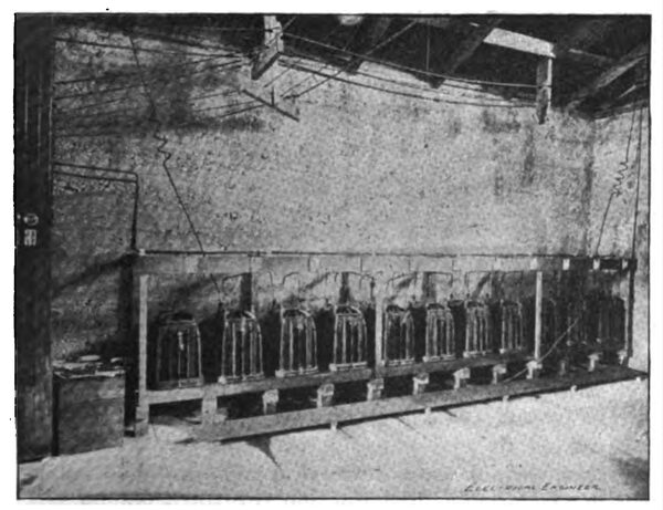
| Bank of 10,000 Volt Transformers. |
emergencies. Clearly then the dual distinction of being the first commencial plant to use 10,000 volts as the normal potential, and of being the longest commercial transmission in the world belongs to the San Antonio Light and Power Company, of California. This is a matter of some gratification to the company, yet more substantial at least is the satisfaction derived from the knowledge that the plant is highly efficient and most successful in every way.
| |||
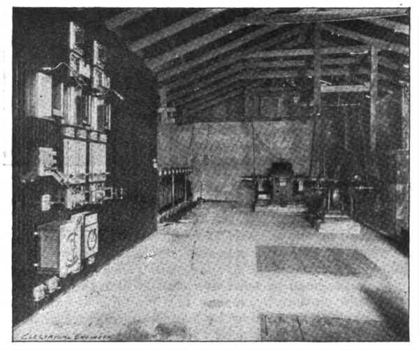
| Generating Station, San Antonio Light & Power Co. |
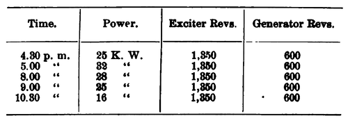
The water for operating this interesting installation is taken from the San Antonio River at a point sixteen miles almost due north of Pomona. A picturesque gorge and waterfall together with a very rapid descent in the river affords a great fall in a comparatively short distance so that by building a tunnel 1,324 feet long and by constructing 2,010 feet of pipe line a head of 395 feet is obtained. The 30 inch two-nozzle Pelton water wheel used was one of the first to be equipped with the new differential governor of the Pelton Water Wheel Company, and in a report rendered by Mr. L. E. Imlay, engineer of the San Antonio Company, appears the following record of test of this governor which, considering that the 200 h. p. wheel was working under only about one-quarter of its capacity, appears noteworthy:
 |
A description of the mechanism will be of interest. The Pelton differential governor consists of four miter wheels geared together. Two of them are loose on the same shaft and are driven by pulleys running in opposite directions the motion of these two wheels being communicated to the wheels placed between them turning loosely on a cross-head. One of the pulleys is driven by an independent motor running at a constant speed. The other pulley is connected to the water wheel shaft either direct or by means of a counter. When the water wheel is running at its proper speed, the revolutions of both governor pulleys are the same, although running in opposite directions, and the cross-head on the shaft is at rest. When any variation in the speed of the water wheel occurs, either above or below the normal, the change in speed will cause the two wheels on the cross-head to turn the shaft which then communicates this motion by means of a pinion and quadrant to the rockshaft, operating by connecting levers either deflecting nozzles or balanced valves and thus controlling the flow of water on the wheel. A small water motor is generally used to drive the constant speed pulley, but in the San Antonio plant it is run from the separately driven exciter shaft, the exciter being coupled direct to an independent 13-inch Pelton wheel. The governor is also provided with an adjustable automatic stop which limits its action on the deflecting nozzle or valve, admitting of its being set so that it will throw the governor out of gear at any desired point at either extremity of action to provide against accident.
| |||
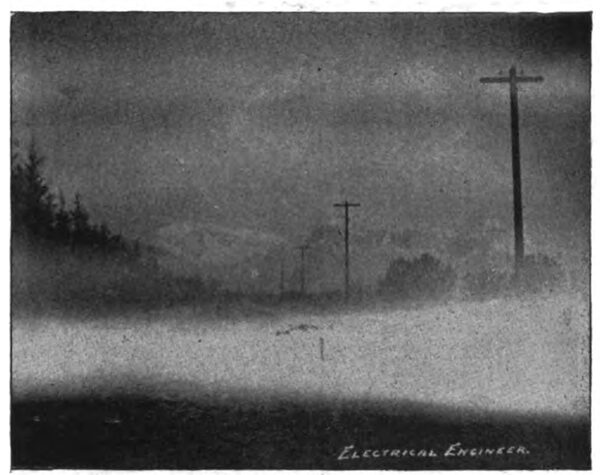
| Pole Line Through San Antonio Canyon Mountain Fog in Foreground. |
The necessity for such provision against accident is evident, as it is plain that if the jet strikes the centre of the bucket squarely and the speed is still slow, the governor will still attempt to raise the nozzle, but to do this will not increase the speed as the jet is at the point of maximum effort. The nozzle, therefore, strikes a stop to prevent further raising and should the governor still continue to act, an accident would ensue, an occurrence which is provided against as stated.
Coupled direct to the large water wheel described, is a standard 120 kilowatt, 12 pole, 1,000 volt Westinghouse alternator which being driven at 600 revolutions delivers current at 7,200 alternations. This 1,000-volt current is taken direct to a switchboard containing the usual Westinghouse central station instruments, whence it is carried to the bank of step-up transformers of the form shown in the accompanying illustration. The whole bank consists of 20 transformers, each having a capacity of six kilowatts and wound so as to take 1,000 volts and deliver 500 volts. The primaries are thrown in parallel across the alternator, and the secondaries are connected up in series, the whole bank of 20 transformers having therefore a potential of 10,000 volts, which is sent to the line. Each transformer is enclosed in oil in an iron case renting upon well grounded iron rails, the cores also being grounded through the case.
From the station are carried two circuits, one to Pomona, 15 miles, and the other to San Bernardino, 28 miles distant. For the first nine miles the circuits occupy the same pole line; then they divide, one continuing southwesterly to Pomona and the other taking an easterly course to San Bernardino. Both these circuits are at present supplied from the bank of transformers described, and are therefore connected in parallel at the station.
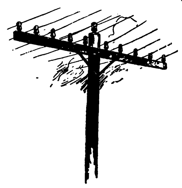
The line consists of No. 7 B. & S. hard-drawn bare copper wire supported on top of special double petticoat glass insulators designed by the Westinghouse Company for this installation. The diameter of the outer and inner bells of the insulators used are 6 and 3 inches respectively. Ordinary Klein iron pins are used, and aside from the large insulators and the special method of supporting the wires, the line presents no unusual feature. Santa Cruz redwood poles, 9x9 inches at the butt and 6x6 inches at the top are generally used, the poles being 25 feet long and set 125 feet apart. The two inside wires are strung 24 inches apart while the two outside wires are separated 18 inches and from the point of divergence the separation is uniformly 24 inches As intimated, the line wires rest in grooves in the tops of the insulators directly over the tops of the pins, thereby obviating all strain to insulators, pins and wires from side connections. No oil insulators are used. In order to avoid trouble that would occur from the settling of dust or its lodgment and adhesion on insulators, all pole lines alongside streets or roads are set to windward of such thoroughfares for the wind always blows in one direction during the dusty season.
In the substations at Pomona and San Bernardino, the form of transformer used is identical with that found at the station and the method of connecting them up is the same with the exception, of course, that the primaries and secondaries are respectively reversed as is necessary to effect step-down transformation. The number of transformers constituting the banks is, however, reduced to allow for the line drop. A potential of 9,500 volts is delivered at Pomona, the loss under present load being 5 per cent., and accordingly 19 transformers have been placed in the bank, while at San Bernardino, the present loss in transmission is 10 per cent., and 18 transformers absorb the 9,000 volts delivered. The potential maintained on city lines is 1,000 volts and in the substations are fonnd all the usual Westinghouse central station appliances, aa well as the Stilwell regulator and compensator.
As might be expected several interesting experiences have arisen which are noteworthy, among which may be mentioned the violent induction in the Pomona circuit when the San Bernardino circuit alone is operated ; the incessant oscillation of the substation voltmeter needles through a considerable arc, while the lamps remain unaffected ; the interesting example of line capacity as shown by cutting out the substation at San Bernardino, connecting the station dynamo to line through the primary of a transformer and burning lamps from its secondary the insulation resistance of the line being above the range of an 11-megohm bridge; and lastly, a new phase of the Ferranti effect showing that the spurious Ferranti potential rises with the current.
| |||
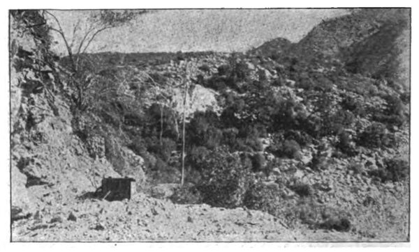
| Outlet of the Tunnel. Pipe Line in Centre of Picture. |
The inception of the project that resulted in the formation oi the San Antonio Light and Power Company is due to Prof. C. G. Baldwin, president of Claremont College, Claremont, Cal., and a member of the Board of Directors of the company. The installation was designed by the electrical engineer for the company, Mr. A. W. Decker, of Sierra Madre, Cal., who early saw the commercial impracticability of the scheme without the use of very high potentials, and to whom must be awarded the credit of having carried out the installation on its present lines. Though supplying current for lighting purposes only, at present, the company is about to engage in power transmission and proposes soon to extend its line in various directions.
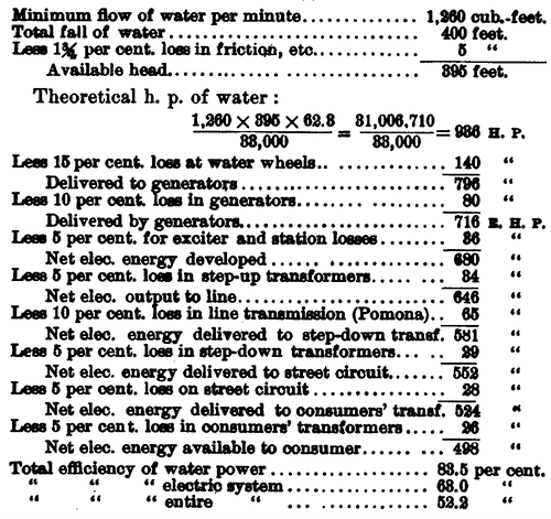
A recent test of the system made by the engineers of the company showed the actual efficiency of the electrical system to be 73.3 per cent. Inasmuch as the detailed figures of the test have not been obtained, it may prove of interest to present the following summary of calculations, taken from the original estimates of the company's engineers. All efficiencies are calculated at maximum working capacity at minimum flow of water. It will be noted that the estimates of losses are extremely liberal:
 |
