[Trade Journal]
Publication: The Electrical Engineer
New York, NY, United States
vol. 16, no. 274, p. 103-107, col. 1-2
WORLD'S FAIR DEPARTMENT.
THE ALLGEMEINE ELEKTRICITAETS-GESELLSCHAFT AT THE WORLD'S FAIR.
Few exhibits in the department of electricity are so interesting as that of the Allgemeine Elektricitaets-Gesellschaft of Berlin. the space occupied is a large one facing on three aisles in the German Section, and the apparatus shown, including everything essential for the generation, transmission, distribution and utilization of current for light and power, aside from its intrinsic worth, affords a splendid opportunity for comparison with that manufactured and used here.
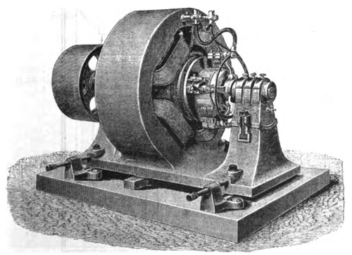 |
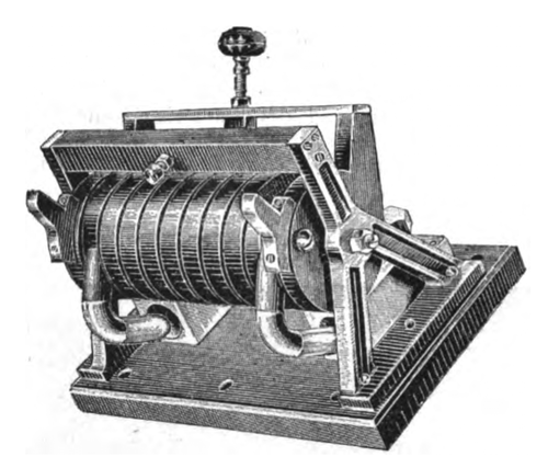
| Fig. 1. 4-Pole Motor. |
For the operation of the moving part of the display current is brought from Machinery Hall to a four-pole shunt motor shown in Fig. 1, wound for 450 volts and 200 amperes and running at 540 revolutions. Fig. 2 shows the motor diagrammatically, arranged for running both forward and backward. The armature is wound with a single layer of rectangular wire so that each individual wire is very near the pole pieces and the efficiency of the motor is said to be 90 per cent.
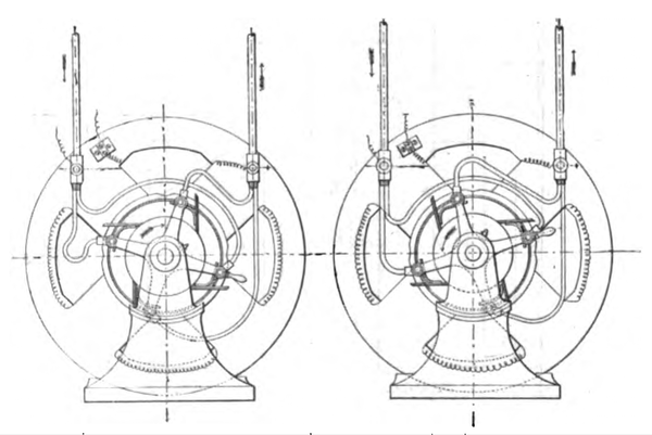 |
| Fig. 2. Arrangement Forreversing Motor. |
From the motor is belted a 100 h. p. three-phase dynamo of 50 periods having 14 poles and wound for 120 volts between each two wires; its field excited by a 110 volt direct current. The armature is drum wound and the core, instead of being notched or toothed, has longitudinal holes bored through it near the circumference, through which the wires pass. The connection is of the open three-phase type, and the efficiency is claimed to be 92 per cent, including the direct current exciter.
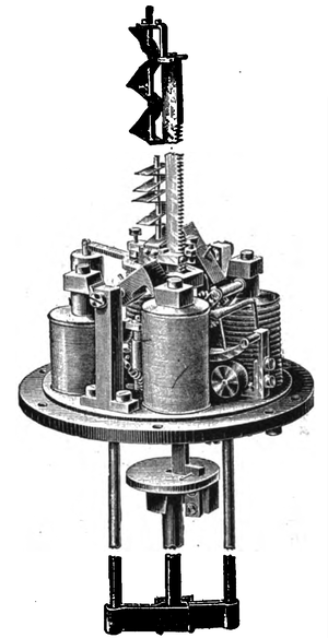 |
| Fig. 3. A.E.G. Differential Arc Lamp. |
Part of the current from this generator goes to a 50 h. p. three-phase motor directly connected by means of a flexible coupling with a 120 volt, 300-ampere direct current generator. The three-phase dynamo also drives a three-phase motor of 5 h. p. directly connected with a Sulzer pump, a 1 h. p. motor with a spring brake to show the torque under load, a 1/2 h. p. motor and one of 1/8 h. p. driving a fan at 700 revolutions. The three last machines mentioned are arranged to reverse under load. All start under full load and only the two largest have starters. They are of the type that were used in the famous transmission work between Lauffen and Frankfort in 1891. Besides the motors this dynamo furnishes current to two 8-ampere alternating arc lamps.
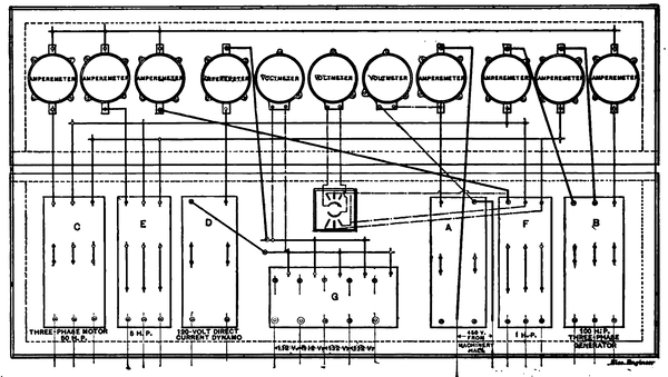 |
| Fig. 4. Diagram of Connections, Main Switchboard. |
The 300-ampere, 120-volt dynamo, mentioned above, operates 400 incandescent lamps and six arcs, two in series two shunt and four differential consuming 10 amperes each besides two other shunt lamps, the smallest ever built, taking but one ampere. The interior mechanism of the differential lamp is shown in Fig. 3. From this 120 volt circuit are run five direct current motors ranging from 1/8 to 6 h. p., all with self-oiling "ring" bearings. In these machines the poles are all connected by an iron ring completely surrounding the armature so that after the brushes are once set they remain fixed and never spark under changes of load. A lot of cooking and heating utensils, cigar lighters, etc., three fan motors and a small drill are operated from this same current.
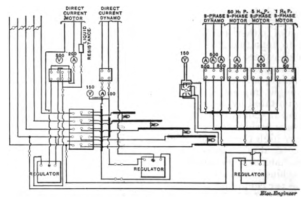 |
| Fig. 5. Circuits of Distributing Board for 3 or 5-Wire Systems. |
The method of connecting the apparatus may be seen by referring to the switchboard diagram, Fig. 4. Here it will be seen that the current from Machinery Hall enters at the switch A, controlling the large motor belted to the 100 h. p. three-phase generator, whose switch is shown at B. The circuits from here may be traced, through the meters, to the switch C, that of the 50 h. p. three-phase motor coupled to the direct current generator whose switch is shown at D; to the 5 h. p. three-phase motor at E, and to the 1 h. p. motor at F. From D the current goes to the distributing switch G, whence it is sent out on either the three or the five-wire system according to the position of the switch. The wiring plan to accomplish this is shown in Fig. 5. Fig. 4 shows the five-wire distributing board with its connections. Fig. 6 is a section of the switchboard shown diagrammatically in Fig. 4.
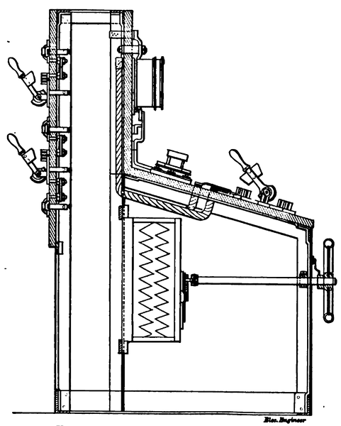 |
| Fig. 6. Section of Main Switchboard. |
We now come to the appliances. Probably the most conspicuous piece of apparatus shown is a large stage-light regulator for theatres by means of which any effect wished can be had by the ingenious combination of switches and resistances. Side, border and footlights are shown with this and twilight, moonlight, full sunlight, storms and lightning are imitated with remarkable accuracy. There are also small portable regulators for halls, etc., where the large instrument would be impracticable or too costly; and projectors, reflectors and color boxes for stage lighting.
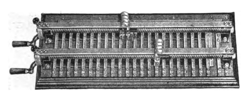 |
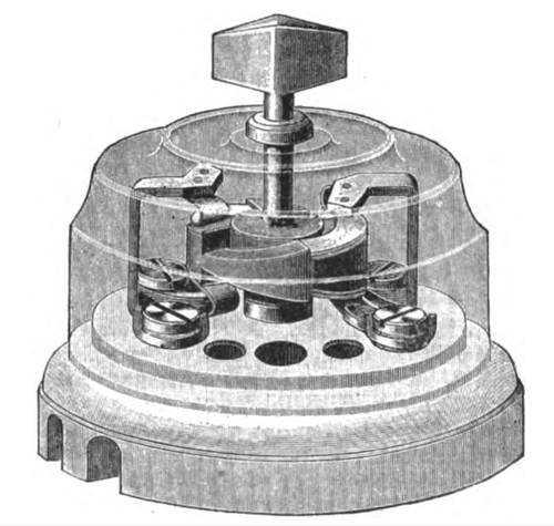
| Fig. 7. Multiple Accumulator Switch. |
 |
| Fig. 8. Automatic Cut Out for Minimum Current. |
A train indicator, now coming into extensive use in Germany to announce the departure of trains from the railway stations, is also shown. The instrument is actuated by clockwork released at the proper moment by an electromagnetic device in the office of the train dispatcher. There are insulation test instruments ranging from 500 to 12,000,000 ohms with standard resistance boxes, standard dry batteries some of which have been in use for the past eight years, and other instruments for station testing. There are ammeters of from 15 to 2,000 amperes capacity and voltmeters for all potentials, portable ammeters for linemen, etc., voltmeters for storage battery work, a photographic registering voltmeter and a self-winding watt-hour meter. A clock-regulating system is shown in which the clocks are simply connected with the incandescent street circuit and are corrected once a day from the central lighting station.
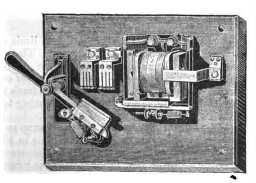 |
| Fig. 9. Automatic Limit Switch for Heavy Currents. |
Considerable space is devoted to apparatus for use in connection with accumulators. There are controlling voltmeters, current indicators for charging and discharging, and several styles of charging switches. One of these, shown in Fig. 7, is so constructed that should the cells of a battery be unevenly discharged, or some exhausted while others are unused and fully charged, the current may be sent only into those cells requiring it and the others cut out of circuit by simply turning the handles at the end and placing the contacts in the proper position. The safety device, Fig. 8, is intended to cut out the accumulators should the dynamo belt slip or anything happen to the engine, and to prevent a flow of current back from the accumulator. It consists of a soft iron core surrounded by a coil of very heavy wire, of practically no resistance, through which the charging current passes, supported on bearings at its ends, on two brass brackets connected by an iron bar. The two ends of the coil dip into mercury cups and in this position complete the circuit. While the current is passing, the iron core is magnetized and its ends are drawn up against the fixed iron bar in front. Should the belt slip, however, there would be an instant when the current, in changing its direction of flow, would be nil and at this instant the iron core, being demagnetized, its ends fall away from the fixed bar, the terminals of the coil leave the mercury cups and the circuit is opened. Fig. 9 is a limit switch intended as a guard against theft of current. The switch, when closed, is held by an electromagnetic device set for a certain number of amperes. Should a greater current pass, the bar holding the switch lever is drawn back releasing the lever and allowing a strong helical spring to open the switch.
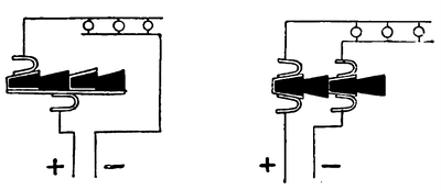 |
| Fig. 10. |
The principle of the single and double pole snap switches made by the company is shown in the diagrams in Fig. 10. They are made in all sorts and varieties. The contacts and contact plates are of brass and the insulation is "Stabilit," a preparation resembling vulcanized fibre, impervious to moisture and unaffected by heat. The construction of the switches is shown in Fig. 11. Knife switches, both double and single pole, are shown, up to 2,500 amperes capacity, and a quantity of house apparatus fusible cut-outs, etc.
 |
| Fig. 11. Single and Multiple Circuit Switch. |
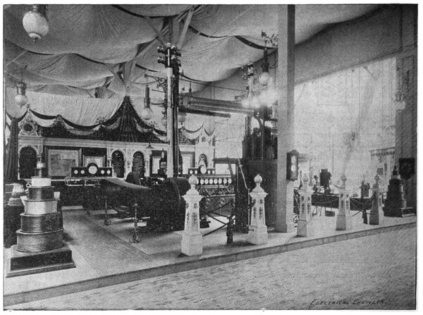
Railway line apparatus is also shown; hangers, pole heads, pull-overs, safety fuses, lightning arresters and car lamps. The appliances are all well made and are rather heavier than those in use here. An overhead distribution plan is shown at the tops of some high poles and can best be understood by reference to the engraving of the exhibit as a whole. A number of reels of wires and cables from heavy armored submarine lighting cable to lamp cord are shown and finally a quantity of miscellaneous specimens of insulation in stabilit and rubber. The former substance seems to be particularly adaptable to the manufacture of accumulator cells and several of these are also shown.
The display is under the direction of Mr. Jacob Sttittner and reflects the highest credit upon his skill and ingenuity as well as upon the recources of the Allgemeine Elektricitats-Gesellshaft.
| |||
| Exhibit of the Allgemeine Elektricitaets-Gesellschaft at the World's Fair. |