[Trade Journal]
Publication: Electrical World
New York, NY, United States
vol. 47, no. 26, p. 1335-1337, col. 1-2
Bishop Creek, Cal., Hydro-Electric Power Plant.
BY J. D. GALLOWAY.
The hydro-electric power plant of the Nevada Power & Milling Co. is situated on Bishop Creek, Inyo County, Cal., about seven miles from the town of Bishop, and the transmission line extends to Goldfield and Tonopah in Nevada. The first generator was placed in operation in September, 1905, and since then power has been supplied the last-named places. The company owns the local lighting plants of the two cities and thus a portion of the load is the lighting circuits, while the balance is stamp mills and mines. While no unusual features are to be noted in the plant it is deemed of sufficient interest to warrant description.
| |||
| Fig. 1. - General View of Pipe Line and Power House. |
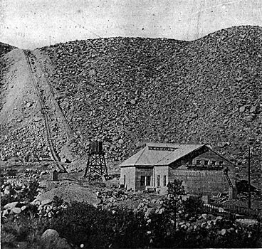
Bishop Creek lies on the eastern slope of the Sierra Nevadas and, with the exception of Owens River, is the only considerable stream on that side of the mountains for several hundred miles. Its headwaters are in the snow of the highest part of the Sierras, which here reach an altitude of over 14,000 ft. above sea level. The plain of Bishop or the Owens River valley lies at an elevation of about 4,000 ft. The mountains rise abruptly from the plain, and the descent of the stream is correspondingly rapid. Its fall is over 1,000 ft. in two miles. This, so far as the writer knows, is the most favorable location in this respect of any power plant in the West.
Water is taken from the creek at a small diverting dam and conveyed along the mountainside in a wooden stave pipe until it reaches a point above the power house, where it enters a. steel pipe that leads to the power house on the creek bank.
The transmission line extends across the valley of the Owens River, then over the White Mountain and across the Nevada Desert to Tonopah Junction, 85 miles. From here the line branches to Tonopah, 18 miles, and to Goldfield, to miles, making the total length of line 113 miles. In crossing the White Mountains the line reaches an elevation of over 10,500 ft.
The pipe line commences at the diverting dam, there being no, flume. The dam is a small concrete structure supplied with four wasteways provided with flash-boards for regulating the height of water. At the present time the supply of water is ample at all seasons of the year, but with an increase of load it is the intention to enlarge this small reservoir formed by the dam in order that it may act as a regulating reservoir. As the load factor on power plants of this description may vary from 0.7 to 1.0, an average being 0.8, a regulating reservoir at the end of the pipe lines becomes a necessity when using stored water.
Water enters the pipe line through an intake chamber at one side of the dam. A screen is placed at the entrance to this chamber, made of ¼ x 1 ½ x 1/2-in. flat iron bars, the vertical bars being placed 2 in. apart and the horizontal bars 1 in. apart.
Back of the screen are three timber gates operated vertically by rack and pinion. The wooden pipe enters the intake through the concrete wall, being built into it in place.
| |||
| Fig. 2. Gates at Head of Pipe Line. |
The pipe line is about 12,000 ft. long, consisting of 6,700 ft. of 42-in. wood-stave pipe, 2,150 ft. of 30-in. wood-stave pipe and 3,150 ft. of 24-in. steel pipe, all diameters being inside measurements. The 42-in. pipe lies on a nearly level grade, the static head at the lower end being about 30 ft. At this point are placed two 30-in. gate valves, one opening into the 30-in. pipe and the other provided for a future line. The 30-in. pipe descends the hill to a point that gives a static head of 265 ft. Here it joins the 24-in. steel pipe which descends a steep hill to the power house, the total static head being 1,068 ft. For about 500 ft. this steel pipe is laid on a slope at an angle of 38 degrees from the horizontal.
The 42-in. pipe is made up of twenty-five staves and the 3o-in. pipe of nineteen staves, milled from a 2x6-in. piece. The lumber is red fir from Southern Oregon and the staves were milled there to the proper circle. The bands are of mild steel of circular section in. in diameter with ends upset to 5/8 in. diameter. They were shipped straight and bent to form at the work. The lugs were of cast-iron of a form that allows the ends of the bands to pass each other and be tightened with nuts on each end. When the bands are tightened there is a slight bending of the rods, but this is not believed to be injurious. The ends of the staves were slotted and a 3/16x1/2-in. compressed paper dowel inserted. When wet this dowel swelled and was very effective in closing leaks.
Bands on the 42-in. pipe were spaced on 6-in, centers, although the pressure did not demand this close spacing. On the 30-in. pipe, which is subject to a considerable pressure, the writer used the pressure due to swelling of wood given by A. L. Adams, 100 lb. per square inch, but in addition to this an allowance was made for initial tension in the rods due to the stress necessary to bring the staves into form. The red fir is a very stiff wood, and by observation it was determined that it was necessary to use 2,100 lb. to bring the staves into position; this was calculated as being distributed along one lineal foot of pipe and distributed among whatever number of bands occurred in that length under different heads. Bands were spaced under these assumptions with a safety factor of four.
The question of initial tension on the rods is believed to be a vital one, as in the case of the stiff lumber used it required much cinching to make the staves come together. As the wood is hard, the bands crush into it but little under pressure and hence there is little relief to the stress. By tests it was determined that, with the wrenches used, an initial tension of 8,000 lb. per square inch could be easily obtained.
The wood pipe is laid directly on the ground, a few sills of culled material being placed at intervals. At points it was covered with earth as a protection from possible rocks rolling down the steep hillsides. The pipe was laid in easy curves, but in one case a curve of 100 ft. radius was made through nearly 90 degrees. For nearly two months the daily amount laid averaged 110 ft.
The wood pipe is provided with two 6-in. and one 30-in. standpipes, the former being of casing and the latter of 30-in. wood pipe. In addition 6-in. air valves are supplied in such number that there is a 6-in. opening every 1,100 ft. On the steel pipe, three 6-in. air valves were placed at the upper end. The material for the wood pipe was mostly hauled to the site on wagons, a minor portion being hauled up from the power house on the tramway used in laying the steel pipe. The steel pipe is 24 in. inside diameter, of lap welded steel and was furnished by the Pelton Water Wheel Co., agents for the makers, a German firm. It is in three thicknesses, 1/2, 3/8 and 1/2 in. The sections are 30 ft. long and the ends are male and female, swelled and of cone shape, so that an angle may be made between sections. The maximum angle turned was 2 deg. 30 min. between two joints. The joints were connected by a single line of rivets, the holes being drilled in the field. The pipe is anchored at intervals by a strap clamped around the pipe and rods, with turnbuckles fastened to bed rock.
 |
| Fig. 3. - Plan and Elevations of Pole Tops. |
 |
| Fig. 4. - Insulator Pins. |
The tramway for raising the pipe from the power house, where it was brought by wagons, was made of discarded narrow-gauge rails and ties laid alongside the pipe trench. The pipe sections were hoisted to place on a single car about 8 ft. long fitted with cables to fasten the joint to the car. The hoisting rope was a single steel cable, and the hoisting was done by an electric hoist made by the Hendrie & Bolthoff Mfg. & Supply Co., of Denver. This hoist was provided with a friction drum of large size and was very effective in handling the loads. The length of the tramway was about 3,300 ft., and as there were several horizontal curves in the line, the cable was held in place by vertical grooved rollers. Rollers were also provided on the straight sections and no difficulty was had with the car returning to the foot of the hill by gravity. Loads of 5,000 lb. were easily handled.
 |
| Fig. 5. - Cross-Sectional View of Power House. |
For drilling and riveting purposes, a compressor operated by an electric motor was provided near the power house and an air-pipe line run to the top of the hill. This line was made of about 500 ft. each of 2-in. and 1 1/2-in. pipe, the remainder being 1-in. This air pipe was provided with connections at intervals, and air drills and air hammers were used on all the work. In laying the pipe, the holes in the female end were drilled in the yard. The section was then taken up on the tramway, laid in place and the male end drilled, after which it was riveted without being disturbed. This gave very tight joints. Progress on this work was slow in the rock trench near the power house, but for a distance of 2,500 ft. the pipe was placed at the rate of 3 2/3 joints laid, drilled and riveted per day. The steel pipe has been entirely covered.
 |
| Fig. 6. - Plan of Power House. |
The power house is a 32x82-ft. concrete building with a 23x52-ft. ell. The roof is of steel, covered with corrugated iron. The main section has a louvre for ventilation. Over the main section is placed a 10-ton, hand-operated traveling crane running on rails supported by reinforced concrete girders of 16 ft. span. The crane was made by the Cyclops Iron Works, of San Francisco. The building, together with the foundations of the machinery and the tail races, rests on a mass of large boulders, bed rock being unknown in the country.
The equipment of the station consists of two 750-kw, 60-cycle, 2,200-volt, three-phase alternating-current generators running at 450 r.p.m. They were made by the National Electric Co., of Milwaukee, the same firm supplying the exciters. In addition there is now being installed a 1,500-kw generator running at 400 r. p. m., supplied by the Allis-Chalmers Co. This generator is shown in the sectional drawing and the location of it and the other machines is shown on the plan. There are two exciters of 60 kw each, delivering current at 140 volts pressure. Both exciters are operated by waterwheels, and in addition, one is provided with an induction motor.
The water wheels for the entire plant were made by the Felton Water Wheel Co., of San Francisco. The two 750-kw machines have Sturgess governors and the 1,500-kw machine has a type Q Lombard governor. Hand-control mechanism is provided for each wheel. Oil is supplied the governors by two oil pumps operated by water wheels. The generators are of the two-bearing type, the water wheel overhanging the tail race.
From the generators the leads are laid in trenches to the switchboard and transformers. The switchboard is provided with ,Westinghouse instruments. The transformers, of which there is one spare, are 500-kw, oil-insulated and water-cooled apparatus, as made by the Stanley-G. I. Co. They are placed on pedestals and rest on iron rollers by which they can be re moved to a car for repairs.
The power lines pass the wall of the building through windows of 28-oz. glass in 36-in. square panes, there being two panes to each window, the outer one with a 6-in. opening and the inner one with a 4-in. opening. The line from the power house to Tonopah is of stranded aluminum equivalent to No. 0 copper. From Tonopah Junction to Goldfield the line is No. 2 aluminum stranded. The insulators are four-part porcelain, 14 in. in diameter held on malleable iron pins. The triangle of the wires is equilateral, with 72-in. sides, and the spans are normally 310 ft. On parts of the line near railroads, cedar poles from Oregon were used and in the mountains native timber. The poles were equipped with a steel channel at the top, bent and fastened to the pole with bolts. The channel supports the top insulator.
The building of this line was done under extreme difficulties, due to heat and absence of water on the desert. The cost of watering a horse amounted to 85 cents per day, and this can be appreciated when it is stated that if a four-horse team started on .a day's haul, a similar team went along with the necessary water for the two.
A telephone line was built parallel to the power line, but on separate poles, and the wisdom of this has been shown this winter. The line is also practically free from the induction usually found where the telephone line is placed on the power line poles.
A switch station was built at Tonopah Junction and sub-station at Tonopah and Goldfield. They are of stone and each contains three oil-insulated, air-cooled Stanley transformers of 300 kw each. Current is reduced to a pressure of 6,600 volts for local distribution.
The line has been operated at a line pressure of 30,000 volts, but when the demand arises for more power, it will be operated at 50,000 volts by connecting the transformers in star.
The officers of the company are: F. J. Campbell, president; G. G. S. Wood, secretary, and C. M. Hobbs, general manager. The main office is at Denver, but the management of the construction was in the hands of Mr. C. M. Hobbs, at Tonopah and Bishop. Mr. C. O. Poole was consulting engineer on the entire installation of the first two units. R. M. Jones, in conjunction with Mr. Poole, designed and located the plant. The had dam, the pipe trench and a part of the wooden pipe were built under Mr. Jones' supervision. The construction of the remainder of the pipe, together with the building of the power house and the installation of the machinery, was carried out under the supervision of the writer, with Mason Galloway as assistant. The installation of the 1,500-kw generator and wheel is under the charge of the writer. The line construction was under the supervision of L. B. Curtis, with J. B. Balcomb and Charles G. Patrick as assistants. The operation of the power house is in charge of J. W. Todd, as superintendent.
Active work was commenced early in March, 1905, and current was turned on the line on September 17, since which time the plant has been in successful operation.
