[Trade Journal]
Publication: Electrical Review
New York, NY, United States
vol. 53, no. 7, p. 243-2481-2, col. 1-2
The Brusio Hydroelectric Plant and Its 50,000-Volt Swiss-Italian Transmission System.II.
By Frank Koester.
CURRENT DISTRIBUTION.
As previously stated, much of the current generated must be transmitted across the boundary line into Italy, and it was deemed advisable to run duplicate circuits to the substation at Piattamala. Since, however, the valley is quite narrow and atmospheric discharges are of great frequency, a tunnel was built for the purpose of carrying these wires to this station.
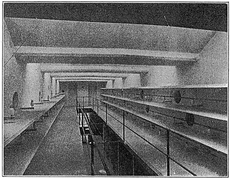
The conductors leave the basement of the switch-room and cross the River Poschiavino through a covered bridge (see Fig. 3), where they then enter the tunnel mentioned. This tunnel, which runs to the substation, is 1,650 feet long. It is 8.2 feet wide and 9.8 feet high, the top being arched.
 |
| Fig. 10.Cross-Section of Cable Tunnel Leading Across Boundary, Between Power-House and Step-Up Transformer Station, Brusio Hydroelectric Plant. |
Owing to the customs regulations between the two countries, the tunnel cannot be entered from the power-house end. Entrance is obtained, however, through a door visible from the street, while at the boundary line the tunnel is closed off by an iron door separating the Italian and Swiss sections. The accompanying cross-section, Fig. 10, illustrates the scheme of arranging the conductors in the tunnel. These conductors consist of copper bars, 0.25 square inch in section, which are carried on petticoat insulators supported on channel irons projecting from the side walls of the tunnel. These channels are spaced longitudinally 4.9 feet, with reinforced concrete slabs spanning them and forming partitions between the conductors. The outgoing feeders tap the middle of the bus-bar system, then are carried on either side of the tunnel to the substation. For the protection of the customs officials the conductors are provided with a removable wire netting.
 |
| Fig. 11.Plan and Elevation, Step-Up Transformer Station at Piattamala. |
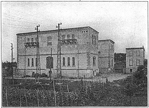
STEP-UP STATION, PIATTAMALA.
As will be seen from the accompanying plan, this station is built in, the shape of a T, 180.5 feet long, 68.8 feet wide and 28.2 feet high, the cross-arm being ninety-two feet long by 42.6 feet high. It is designed to accommodate twenty-four single-phase transformers having a capacity of 1,250 kilowatts each. At present there are thirteen installed, with a total normal capacity of 16,250 kilowatts.
At one end of the transformer room is the meter room, where the current is checked by the two companies. The transformers are arranged in two rows, between which are two tracks leading into the inspection and repair room. This is in the middle of the cross-arm of the T, in which there is a ten-ton traveling crane.
The transformer-switchboard rooms are directly behind each row of transformers. From the illustration it will be seen that the substation is divided into two distinct sections. The outgoing feeders leave the building from the third story of the cross-wing.
| |||
| Fig. 12 Step-Up Transformer Station, Piattamala. |
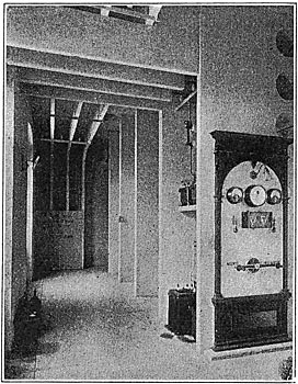
The feeder lines from the power station enter the substation from the tunnel on the ground floor, as the station (Fig. 12) is built into the hillside. As two companies are concerned in the amount of current used, the Brusio company supplying the power and the Societa Lombarda receiving the current for distribution, this room, on the second floor, is thoroughly equipped with measuring instruments, some of which are kilowatt meters of different makes, and are switched in series in order to check each other.
The meter switches are so arranged that the current may be thrown onto either row of transformers from either of the two feeder lines, or the current from both feeders may be thrown on one row of transformers only. The oil switches in the meter room are of the remote-control, hand-operated type. It was not deemed advisable to install automatic switches, because a sudden cutting out the whole load, which might amount to 20,000 kilowatts, might seriously interfere with the operation of the plant, particularly the hydraulic end.
| |||
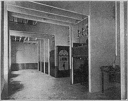
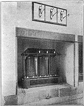
| Fig. 13.-Switch Room at the Step-Up Transformer Station at Piattamala. |
| |||
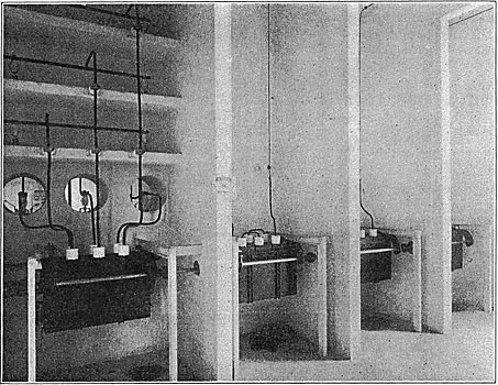
| Fig. 14. Fifty-Thousand-Volt Water-Flow Lightning Arresters at Step-Up Station, Piattamala. |
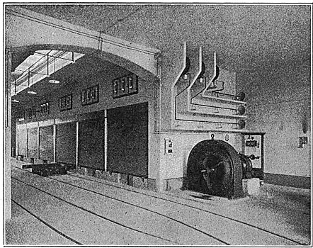
Above the aisle, between the two rows of transformers, and extending the full length of the room, is a mezzanine floor carrying the feeders in two vertical rows, one on either side, to the transformers. The phases of the bus-bar system are separated by concrete shelves, the front remaining open. The high-tension, or 50,000-volt, bus-bars run on the mezzanine floor above the transformer switchboard or operating rooms. These bus-bars are arranged in horizontal rows separated by concrete partitions but not covered.
The transformers are of the Alioth water-cooled oil type, a system of water circulation from a spring under a head of twenty-six feet being provided. The efficiency of the transformers under actual test at full load was 97.5 per cent; at half load, 96.5 per cent. The drop in voltage between no load and full load with a power-factor, cos Ø = 1 is one per cent. With cos Ø = 0.8 is 2.2 per cent. The greatest drop is 2.8 per cent.
| |||
| Fig. 15. Railway Crossing.. |
Each transformer is contained in a well-ventilated concrete compartment, the front being provided with a corrugated-iron rolling shutter. The transformers are provided with pinion wheels resting on pairs of racks secured to the floor, the transfer table also being provided with such racks. This device greatly facilitates the handling of the transformers, a ratchet being used for moving them onto the transfer table by which they are transported on the track to the inspection and repair room, where the cores are easily taken out by the overhead crane.
| |||
| Fig. 16.Span Over River Adda Below Lecco. |
Each transformer is provided on the low-tension side (7,000-volt) with a three-pole oil switch, while on the high-tension side (50,000-volt) three oil switches, one for each phase, are provided. These switches, interconnected, are remote-controlled, and may be operated either by hand or automatically. Access to the 7,000-volt switches, which are protected by doors, can only be had when the current is off. The 50,000-volt switches are similarly protected. All these switches are accessible from the aisles of the operating rooms. Between each group of transformers sectionalizing switches and choke-coils are provided for protection against variations in load caused by throwing the switches.
| |||
| Fig. 17.Street and Telephone Crossing Near Lecco. Also Section Switch House. |
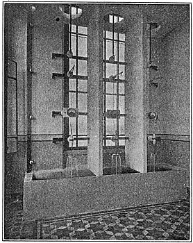
On account of the high tension and long transmission line, the great variation in altitude and consequent difference in temperatures, and particularly on account of the frequent storms and atmospheric discharges, various devices were installed for protection against surges. For this purpose the choke-coils above mentioned are placed on each side of the transformers, and horn lightning arresters are placed on the outgoing feeders. The latter have a gap of two and three-eighths inches and are connected in series with water-flow resistances. The choke-coils consist of two spools, having a brass core, upon which is tightly wound a copper band of sixty turns, separated by insulating material, thus forming a solid tightly wound spool which sudden surges will not distort. For taking up lighter static and atmospheric discharges, the more sensitive roll lightning arresters were installed and connected in series with water-flow resistances. Finally, as all surges will create more or less variation in pressure, water-flow rheostats are installed for each phase to maintain a uniform pressure. This apparatus consists of a nozzle for forcing a jet of water, under a head of twenty-six feet (supplied from above-mentioned spring), against a baffle-plate connected to the line. The stream of water is three-eighths inch diameter and twenty-eight inches high and allows a leakage of one-tenth ampere. Ammeters are inserted in the wire connection to this apparatus in order to detect failures in the grounding. All lightning arresters, as well as the outgoing lines, are provided with disconnecting switches. All metallic features of the installation are interconnected and well grounded. Figs. 13 and 14 show switch-room and water-flow rheostats at Piattamala.
| |||
| Fig. 18.Step-Down Transformer Station at Lomazzo. |
TRANSMISSION LINES.
The transmission line (50,000-volt) may be considered the most important in Europe. It consists of two independent lines, each 88.5 miles long. As the line runs over mountains and valleys, the peaks were avoided as much as possible to escape the unavoidable difficulties due to atmospheric discharges. These lines cross three provinces and ninety-four townships, and required the right of way through 6,000 properties, the cost of which averaged about $800 per mile. The lines cross ten railways, one tramway, ten state roads and 120 county roads.
| |||
| Fig. 19.Fifty-Thousand-Volt Switch Room at Lomazzo. |
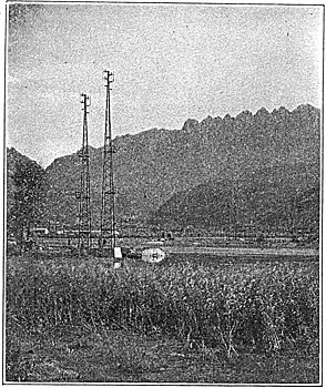
Prom the main substation at Piattamala the line runs westward through the Adda Valley to Colico, thence along the shore of Lake Como to Bellano, from which point it runs in a southeasterly direction over the Valsasina Plateau. Palasco, the highest point of the line, is 2,130 feet above sea level. From Valsasina the lines run in the mountains of Lecco in a southwesterly direction and cross the Adda Valley with a span of 720 feet, this being the lowest point of the line (640 feet above sea level). From here until the first step-down station, at Lomazzo, is reached, 84.5 miles distant from the step-up station at Piattamala, the run is practically straight. Eight and one-half miles beyond Lomazzo, at Castellanza, is another step-down station.
The average span is 393 feet. In eighty-seven cases, however, the span exceeded the average, the longest span being 1,280 feet, across the Gravina Valley at Colico. The transmission line consists of two parallel rows of towers, from thirteen to 16.5 feet apart, of latticed-girder construction imbedded in concrete. Each tower is provided with six brackets, three for present use and three for future extension; so that there will be eventually four separate three-phase circuits. The porcelain insulators are supported on pins, fastened to oak and chestnut blocks secured to the steel brackets. Each cable consists of nineteen wires, 2.6 millimetres in diameter, the total diameter of the cable being fourteen millimetres (105 square millimetres area).
| |||
| Fig, 20.Transformer Room at Lomazzo. |
The towers are calculated for a wind pressure of seventy miles per hour, allowing a stress in the copper of 8,500 pounds per square inch and on the tower of 17,000 pounds per square inch. Allowance is made for a temperature difference of 120 degrees Fahrenheit. On account of the difference in the spans and frequent changes in direction of the lines, four different types of towers are employed, weighing from 1,250 to 2,500 pounds each. There are a total of 3,100 towers, averaging in price $80 each, including foundation and erection. The two existing lines represent 900 gross tons of copper and 10,000 insulators at $2.60 each, including mounting and wooden blocks. The laying of the cables cost $128 per mile of transmission.
The transmission system is divided into six sections, varying from 8.5 to 25.5 miles, and is provided with section switches, arranged so that in case of a break in a section of one line the current may be by-passed over the other line. There is a small station at each section for housing the sectionalizing switches, measuring apparatus, lightning arresters, some of which are of the horn type, some of the coil type and some are also provided with water-flow rheostats as described previously.
| |||
| Fig. 21.Bus-Bar Arrangement at Lomazzo. |
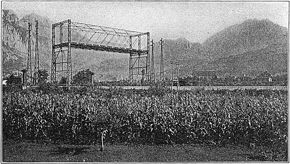
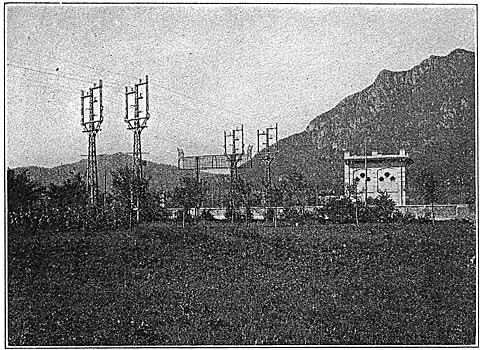
At a distance of sixty-five feet and parallel with the high-tension lines, a telephone and telegraph line is carried the entire length of the transmission system for the exclusive use of the plant. There are two wires carried on wooden poles and thirty stations costing $30 each, while the line costs about $380 per mile. Fig. 15 shows the transmission line crossing the railway. Fig. 16 shows the long span over the River Adda. Fig. 17 shows the transmission line crossing the street and the telephone wires, and also a section switch house near Lecco.
TRANSFORMER STATION, LOMAZZO.
This substation is located centrally in the low-tension distributing district. It is built in the form of an I. The wing at one end containing the apparatus for the incoming feeders is eighty-five feet by thirty feet, and forty-eight feet high. The wing at the opposite end is of the same dimensions and contains the apparatus for the outgoing feeders. The middle member of the building, containing the transformers, is fifty-five feet wide by sixty feet long and thirty-three feet high. The over-all dimensions are eighty-five feet by 120 feet.
The two 50,000-volt circuits enter the second floor of one of the wings in a way similar to the outgoing feeders leaving the step-up station at Piattamala. The feeders are similarly protected against electrical discharges, excepting that the water-flow lightning arresters are sup plied with water by a centrifugal pump and tank under a head of forty feet instead of a natural head from the mountain stream. The transformers (1,250 kilowatts, 50,000-11,000 volts) are arranged in two rows, similar to those at Piattamala, with tracks in front of the compartments, of which there are six on each side. There are also six three-phase transformers of 5,000 kilowatts each (11,000-20,000 volts). There are at present installed only three single-phase and three three-phase transformers. While the transformers at Piattamala are of the oil-cooled, water-circulating type, those at this station (Lomazzo) are of the forced-air-cooled type, for which two blowers are at present installed. The final equipment demands four blowers, of which two will be kept in reserve. The blowers are motor-driven and discharge through air ducts located beneath the two rows of transformers. The cores of the transformers are not encased. The fronts of the transformer compartments are provided with rolling shutters, and ventilators are placed in the roof. Good results were obtained with these transformers, an advantage being that the cores can be easily inspected. The primary winding is provided with taps so that the voltage may be reduced to 35,000. This was done so that easy regulation might be secured: The tests show that the efficiency at full load is ninety-seven per cent and at half load 96.5 per cent. The pressure loss at full load with a power-factor of cos Ø = 1 is one per cent, and with a power-factor 0.8 it is three per cent. The temperature rise is forty degrees centigrade. The high and low-tension sides, respectively, were tested to 65,000 and 17,000 volts, ten minutes' duration. The transformers are capable of standing an overload of twenty-five per cent with a total temperature rise of sixty degrees centigrade. The operation of the blowers is included in the above-named efficiencies.
| |||
| Fig. 22. Five-Thousand-Kilovolt-Ampere, Open-Type, Air-Cooled Transformer at Lomazzo. |
The 11,000-20,000-volt, 500-kilowatt, three-phase transformers have an efficiency of ninety-seven per cent at full load with a power-factor of cos Ø = 1, while with cos Ø = 0.8 is ninety-six per cent and three-quarters load ninety-six per cent and ninety-five .per cent, while at half load it is 95.5 and 94.5 per cent. The drop in pressure is 1.5 per cent with a power-factor of cos Ø = 1, and three per cent with a power-factor of 0.8. The temperature rise is fifty degrees centigrade and the overload capacity is twenty per cent for two hours.
The wiring diagram is made so that under normal operating condition the line "A" will distribute 11,000-volt current in the district about Lomazzo, and "B" and "C" will supply Castellanza. The arrangement is such that one bus-bar system may feed either of the outgoing lines, or that the line "A" to Lomazzo may be fed from line "C." Through the line "C" 11,000-volt current may be drawn from the steam-power plant at Castellanza, of the Societe, Lombarda, which is a reserve for the hydraulic plants at Turbigo and Vizzola. It will be seen that with this auxiliary source of supply, in case of emergency current may be sent through this station (Lomazzo) and through the station at Piattamala to the hydraulic plant at Brusio.
A fourth line of 20,000 volts leads northward to Como, for which purpose the three-phase 11,000-20,000-volt transformers were installed.
The feeders from the 50,000-11,000-volt transformers lead to the three-pole oil switches on the mezzanine floor above the aisle between the two rows of transformers. The feeders to and from the transformers are provided with cut-out switches.
| |||
| Fig. 23.Switch Group, 11,000-20,000 Volts, at Lomazzo. |
The 50,000, 11,000 and 20,000-volt bus-bars are arranged, according to the space available, in horizontal or vertical rows, and the phases are separated by concrete shelves or partitions. Three bus-bar compartments remain uncovered. The 20,000-volt outgoing feeders are protected like those at the step-up station at Piattamala. Fig. 18 shows the step-down transformer station at Lomazzo, Fig. 19 shows the 50,000-volt switchroom, Fig. 20 shows the transformer room, Fig. 21 shows the bus-bar arrangement, Fig. 22 shows the 5,000kilowatt-ampere air-cooled transformers, and Fig. 23 shows the 11,000-20,000-volt switch group.
TRANSFORMER STATION, CASTELLANZA.
As previously stated, the Societa Lombarda possesses a steam-power plant at Castellanza having an equipment of two 2,500-horse-power engines and two 5,000- horse-power steam turbines, which work in parallel with the above-described hydroelectric plants at Brusio, Turbigo and Vizzola. A temporary transformer station has been erected in the engine room of this power-house containing six single-phase, 1,250-kilowatt transformers arranged in groups of three. The whole apparatus, owing to the small space available, has been located on three floors. The transformers, which are of the oil, water-cooled type, are designed similarly to those at Piattamala, except for a voltage of 11,000-40,000. Taps are provided so that some coils may be cut out to secure a voltage of 35,000. The efficiency of the transformers at full load is ninety-eight per cent and at half load ninety-seven per cent. The drop in pressure at full load and with a power-factor of cos Ø = 1 is one per cent, while with cos Ø = 0.8 it is two per cent. The rise in temperature is forty-five degrees centigrade, using five gallons of water in twenty minutes at fifteen degrees centigrade. They are capable of standing an overload of twenty-five per cent, maintaining the temperature of forty-five degrees centigrade, and using ten gallons of water, or with a rise of temperature of sixty degrees using five gallons of water. The transformers were tested at 65,000 volts for a duration of ten minutes.
Okonite insulation has been used throughout this station.
As the capacity of the steam-power plant is expected to be increased in the near future, an isolated transformer station is now being erected alongside of this power-house which will accommodate eighteen transformers.
The entire installation was put in operation within two and one-half years from the organization of the company, and is giving most satisfactory results; the expectation being that the maximum output will be reached during this year.
The entire plant was installed in accordance with the plans of the "Electricitats Gesellschaft Alioth, A. G.," Mǜnchenstein, Switzerland, which also furnished the bulk of the electrical equipment.
