[Trade Journal]
Publication: Electric Railway Journal
New York, NY, United States
vol. 40, no. 7, p. 248-250, col. 1/2
New Third-Rail and Contact-Shoe System of Philadelphia & Western Railway
Details of an Economical Under-Contact Third-Rail System with a New Type of Automatic Shoe
The Philadelphia & Western Railway recently found itself confronted by the necessity either of rehabilitating the under-contact third-rail which had been originally installed and was of U shape or of using some other type. The decision had to be hastened because of the fact that the company was about to build 6 1/2 miles of double track as a final link of the system over which the trolley cars of the Norristown Transit Company and the Lehigh Valley Transit Company would enter Philadelphia, so that an exceptional opportunity was offered for changing over the entire line at the lowest ultimate cost. A decision was finally made in favor of the top-contact rail hereinafter described.
CONDITIONS TO BE SATISFIED BY NEW THIRD-RAIL SYSTEM
The features which had to be embodied in a system of contact-rail current collection were as follows: Reduction of first cost and maintenance, elimination of leakage losses, increase in clearance, automatic operation of the shoes.
 |
| New Third-RailClearance Lines on Branch Lines Where Original Contact Rail Has Been Reversed |
 |
| New Third-RailClearance Lines on Main Line, With New Section of Conductor Rail |
It was found possible to design a top-contact third-rail at a much lower cost than that of the original pattern.
Before the company finally decided upon this form, however, it made a careful cost comparison of catenary construction and of the various types of third-rail systems in use throughout the country. It was found that for approximately 17 miles of double track the simplified third-rail system (using part of the old material) could be installed for about $100,000 less than catenary construction. The cost of the new shoes, hereinafter described, is about one-half the cost of the original type.
 |
| New Third-RailCross-Section of Old Contact Rail |
Experience had shown that while the original under-contact rail provided for longitudinal movement due to expansion and contraction, no provision had been made for movement in a vertical plane. The vibrations set up by heavy cars brought such enormous strains upon the insulators that in many places the only insulation left was that afforded by the tie. Furthermore, it was found very difficult to locate these defective insulators.
 |
| New Third-RailSide Inclines for Crossing From One Rail to Another |
As to clearances, it was desirable that the tracks of the Philadelphia & Western Railway, which are built in accordance with the highest steam railroad standards, should also be able to take the various types of steam railroad freight cars. Sufficient clearances for this purpose could not be obtained with the existing under-contact rail. The clearances of the new rail, as shown on this page, extend beyond the clearance line specified by the American Electric Railway Association and the American Railway Association. In fact, they are ample to take care of all classes of rolling stock except a few types of the hopper-bottom cars usually referred to as "battleships."
 |
| New Third-RailEnd Inclines and Bonds |
As to the change in the shoe, the automatic folding and unfolding feature was a necessity, owing to the agreement for interchange service with the Norristown Transit Company. The Norristown Transit cars operate with an overhead trolley on their own lines, and it was essential to have the interchange from third-rail to overhead trolley effected without danger or any loss of time. It is especially desirable that the shoes on such cars should be folded when the cars are operating on overhead trolley wire and on city streets, as their projection beyond the clearance lines of the car is likely to lead to accidents. It would not be desirable, of course, to fold the shoes by hand.
In view of the acknowledged superiority of the covered under-contact rail from the standpoint of protection against sleet trouble and safety to employees, it was also felt that the same advantages must be embodied in the new top-contact rail.
DETAILS OF NEW THIRD-RAIL
The new third-rail system as now installed in accordance with the designs of H. S. Farquhar, general manager and chief engineer Philadelphia & Western Railway, has two types of conductors. One is a 75-lb. T-rail used for the entirely replaced construction on the main line between West Philadelphia and Villa Nova; the other is the original special U-section which was taken off this main line and installed on the branch lines upside down, owing to the change from bottom to top-contact. These conductors are made of special steel having a conductivity of about 25 per cent of 98 per cent pure copper and are shown on page 248. They are supported at intervals of about 8 ft. on either of the two types of insulators illustrated. The block type and petticoat type of insulators furnished by the Ohio Brass Company are of the one-piece dry-process manufacture. The petticoat type is believed to be the largest single piece of porcelain ever made of this character. This insulator is pressed from a dry clay which is practically a powder. The petticoat type of insulator, furnished by the Pittsburgh High-Voltage Insulator Company, through the Shield Electric Company, New York, is a two-piece, cemented porcelain wet-process insulator. All insulators are giving good service. The insulators are held in place on the tie by means of a cast-iron cup and lag screw, and a cast-iron cap on top of the insulator retains the rail in position.
| |||
| New Third-RailBending-Down of Third-Rail at Villa Nova Junction |
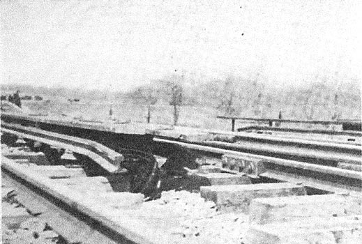
The vibration which gave so much trouble in the original third-rail system has been obviated by an allowance for ample vertical movement and also by the insertion of a canvas pad between the cap and the insulator. This pad prevents the vibration of the cars and track structure from acting directly upon the porcelain. The conductor rails are not brought down to a point at switches or other special work, the rail being merely bent down at the ends as illustrated. The rails are bonded with the electric welded bond of the Electric Railway Improvement Company, one 300,- 000-circ. mil bond being placed on each side of each joint of the 75-lb. conductor and one at each joint of the U-conductor. In crossing from one third-rail to another, side inclines consisting of sloped timbers placed alongside the conductor rails are provided.
 |
| New Third-RailSingle-Piece and Double-Piece Insulators |
Protection for track walkers and practical elimination of sleet, ice and snow troubles are insured by two 2-in, cover boards which are carried from mild steel brackets, as shown on page 248. This arrangement of cover eliminates joint plates as the joints of the boards are staggered, prevents warping and permits the cover board to be readily sprung around curves.
THIRD-RAIL SHOE
The construction of the self-folding top-contact shoe is shown in the sections on page 25o. It will be seen that the shoe slipper is pivoted to a connecting rod, the spring of which makes the slipper bear against the contact rail with a pressure of about to lb. Although this is the only spring in the shoe, it holds the slipper in both its operative and inoperative positions and has proved ample for the service. The spring is fully protected by means of the special spring chamber from becoming packed up with snow or ice, so that the annoying necessity of using burning waste to thaw out any springs is obviated. The complete slipper does not bear directly on the rail, as it carries a tool-steel insert wearing piece which is retained by two rivets. When this piece is inserted, babbitt is poured into the grooves, as indicated in the section, to hold the wearing part more firmly and to give perfect electrical contact.
 |
| New Third-RailSide View Showing A Joint, Bond and Insulator |
During the winter the slipper is slanted slightly downward in order to make contact with the far side of the third rail, as from observation this part of the rail is usually found entirely free from sleet. This is done by means of the eccentric stop, the four quarter turns of which will also take care of a 172-in. reduction in the diameter of the car wheels. In addition to the eccentric stop there is a rack adjustment on the car trucks for raising and lowering the shoe beams.
 |
| New Third-RailAutomatic Shoe, Open and Closed |
The automatic folding and unfolding of the shoe is obtained in the following manner: Where the shoes should either open or fold, as the case may be, two parallel metal strips which are sloped in opposite directions are placed along the tracks and set several inches apart. If the shoe is open, the slipper will bear against the rising strip until it assumes a nearly vertical position, and the spring then acts to close it. The rising of the slipper, however, is coincident with the lowering of a tail-piece which is always approximately at right angles to the slipper. When the shoe is to be opened, this tail-piece will be within the range of the other inclined strip, so that it will be forced upward while the slipper moves downward to make contact with the conductor rail. The eccentric stop and the tail-piece prevent the slipper from dropping when unsupported by the third-rail.
 |
| New Third-RailUpper Views, New Top-Contact Shoe Closed and Open Lower ViewsLeft, Under-Contact Shoe Right, Compromise Shoe |
An effective proof of the simple construction of the new shoe is afforded by one of the accompanying half-tone views which shows the original under-contact shoe, the compromise shoe which was used during the change-over period when the shoes had to operate on both under-contact and top-contact rails, and the present automatic folding shoe in both its open and closed positions.
