[Trade Journal]
Publication: The Electrical Engineer
New York, NY, United States
vol. 27, no. 563, p. 187-189, col. 1-2
European Transmission Practice and the Water Power and Electric Plant at the Adda Rapids Near Paderno, Italy.-II.
(Concluded.)
ONE of the most remarkable parts of the plant is the switch boards. The importance given to switchboards is of quite recent date, and arises from the latest experience in materials. In the first stations where large currents at high pressure were used, no greater importance was given to the switchboards than to those for ordinary lighting stations. But the numerous difficulties that arose gradually proved that in such installations the switchboards represent one of the most delicate parts of the whole plant. Consequently they ought to be designed very carefully, without sparing expense, and provided with plenty of room. The switchboard at Paderno, built on these lines, has an area of about 17 square feet, and is fixed in a large opening in the middle of the wall of the dynamo room. The dynamo instruments are placed on a gallery 9 feet 6 inches above the floor, while those for the line are placed on the other side of the switch board room. The dynamo switchboard is divided into nine panels, of which seven belong to the seven alternators, while the other two are used for the bus- bars and are fixed in the centre of the board.
Each of the panels of the dynamo board carries the following apparatus and instruments: One double-pole high tension switch, three fuses, one change- over switch, one regulator for the exciting current, one regulator for the exciter field, one switch board transformer, one voltmeter, one ammeter, one wattmeter for the alternating current, one ammeter for the exciting current, one voltmeter and synchronizing lamp.
| |||
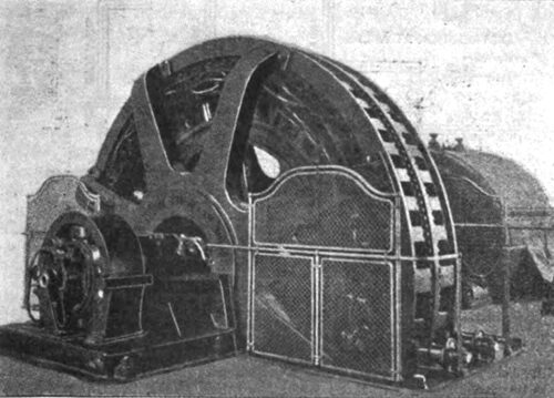
| Brown, Boveri & Co. Generator at Paderno, Italy. |
These are more or less the apparatus and instruments which are found on all the panels; some, however, merit special notice. With regard to the switch, it may be remarked that all currents at a low voltage can be broken without difficulty because the pressure is not sufficient to maintain an arc when the two contacts of the switch are at a little distance from each other. Small currents at very high voltages can also be broken without special apparatus, because up to a certain limit they lack the necessary energy to overcome the resistance of the air. But when both pressure and current are large the case is different. With 3,500 volts and 150 amperes one gets an arc which may exceed 3 feet in length, and with 8,000 volts and 80 amperes an arc which exceeds 5 feet. When those enormous arcs are developed between two parts of a switchboard, they are carried up wards by the action of the hot air, and pass through any conductors they may encounter, melting metals, smashing insulators and burning wood and rubber.
The length an arc may assume depends, first of all, on the nature of the dielectric in which it occurs. It depends, in the second place, on the material of which the electrodes are composed; thus, if the electrodes are of copper we get a much longer arc than if they are of carbon, because the copper vapor, which volatilizes and burns, forms a path of higher conductivity than that formed from particles of carbon. And here we find an explanation of the efficacy of quick break switches. With a quick break switch of the type of the General Electric Co. a current of 70 amperes at 3,600 volts is easily broken, but if it is done slowly with the same switch the arc cannot be extinguished, because, with the increase in rapidity of movement, the formation of copper vapor is rendered much less. The principle of a quick break in oil is employed in the construction of the high-pressure switches at Paderno.
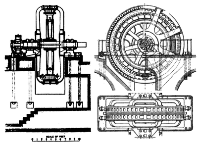 |
| Paderno Generator. |
Safety fuses present an analogous problem, but, fortunately, the solution is very safe and simple. The fuses made by the firm of Brown-Boveri & Co. have given such a perfect action at 5,000 volts as to justify considerable confidence in their action at higher pressures. The fuse wire is stretched out in an open tube of composition or of porcelain. When the fuse goes the arc thus formed instantaneously expands the air contained in the tube, and causes a kind of explosion which causes the arc. On the left of the board there is a change-over switch, which embodies some novel features. The whole of the installation, commencing with the switchboards of Paderno going step by step to Porta Volta and Santa Radegonda, has been designed so that there may always be the possibility of splitting up the supply into two distinct parts. The bus-bars are in duplicate, and each dynamo may be connected up to either of the two. Thus the lines, as well as the transformers at Milan, the dynamos at Porta Volta, etc., can be separated from each other. This has been designed so as to keep the two supplies distinct, should only supply have special requirements, or be a source of dis either supply have special requirements, or be a source of disturbance to the other.
The wattmeter on the switchboard of each dynamo was introduced more with the idea of giving a true relative indication of the load of each alternator than to give an absolute reading, because when several alternators are running in parallel, the am meters give very little indication of the true load on the machines, this being affected by the difference of phase. The electrostatic voltmeters placed on the main switchboard measure the pressure at Milan. Three pilot wires are fixed on the posts under the principal conductors, and connect the voltmeters directly with the secondary circuit at 150 volts placed in the station of Porta Volta. These are of very great importance because it is according to their readings that the pressure at the station is regulated.
Behind the row of dynamo switchboards are fixed the line switchboards. The lines are six in number, and each one has its own switchboard with change-over switch, fuses and ammeters. All the switchboards are in general accessible where possible; each section may be completely separated from the others which are live, so that a man can work on them or clean them with perfect safety. They are all made of iron, porcelain and marble, and no combustible material is employed. The connections are all made of rigid bars and the tout ensemble symmetrical, simple and mechanical.
The lines run from the switchboards into a room above where the lightning arresters are placed; from thence they pass through suitable openings placed in the back wall of the room to the first post. As we have already said, the number of wires in the line will be 18. A high tension line of this description intended for an important public supply, like that of Milan, had to be designed with special care and precautions to avoid breakdowns; it was not only necessary to have the line well made, but to have a line which could be repaired without interrupting the supply. From the station of Paderno and that of Porta Volta runs a double row of posts; each row carries nine wires, and is at a distance of 6 feet 6 inches from the other. When it is necessary, from any reason whatsoever, to work on one of the lines, the whole of the section to which it belongs can be cut out of circuit, and the supply carried by the other half alone. At times of heavy load in such cases there will be a greater drop of pressure, but this has been provided for by the possibility of increasing the pressure of the alternators to 15,000 volts.
In the early alternate current installations, the line was one of the chief sources of failure, and that because not even a remote idea was entertained of the importance of the effects of mutual and self-induction. It is curious that although academically the case had been worked out some time before, yet among the lines proposed by the different manufacturing firms there were solutions perfectly diverse and contradictory. Now all this part is well enough known, so that it is possible to proceed with perfect safety. It is recognized that, in order to have a weak, small inductance, the wires must be of small diameter and far apart, necessitating, in the case of heavy currents, a considerable number of wires. Then there is another very important point, and that is, when the wires are numerous they must be arranged in such a manner that the effects of induction are equal on all. If not, there will be a tendency to produce idle currents between the wires belonging to the same branch of the system.
The theoretically perfect arrangement of a number of conductors carrying three-phase currents would be that in which each conductor was placed in the same condition of induction with respect to the others. A cross-section of the arrangement would show all the wires placed at equal distances on a circle. This form of grouping the conductors, although possible to realize, is not very practical, especially if the number of wires is great. The form which, after the circle, gives the smallest mutual induction between the different wires of the same branch is that well known method in which the wires are arranged in the form of a triangle. This is the arrangement actually adopted on the Paderno line. The wires are 0.354 inch diameter, and the distance between the nearest is 2 feet. They are of electrolytic copper of 98 per cent. conductivity, and are fixed up in such a way as to have, with a span of 197 feet, a dip which varies from 2 feet in the hardest winter to 4 feet in the hottest summer.
In lines for alternating current it is necessary to consider the loss of energy as well as the drop of pressure. The loss of energy is the product of the resistance by the square of the current, and will be about 9 per cent. at full load when the power factor is 80 per cent. The expression for the drop of pressure is somewhat more complex. The special case was studied by the late Prof. Ferraris, and the resulting calculation is of the highest interest. In this calculation the branch of the three-phase system to which each wire belongs must be taken into account, because the effect of mutual induction is a function of the positions of all the nine wires, the relative distances and the currents which flow through them. The drop of pressure is a function of this coefficient of mutual induction, the ohmic resistance of the wire, the current, and lastly the difference of phase caused by an inductive load. All these quantities properly combined give as a result the drop of pressure which in our case is about 12.5 per cent., which the loss of energy is only 9 per cent.
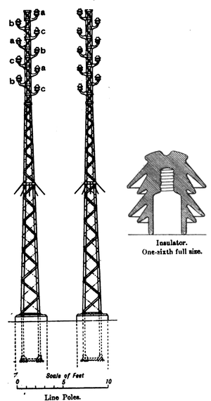 |
| Poles and Type of Insulator Used on Paderno Transmission Line. |
This is one of the first lines in which entirely metallic masts are used. Although the fall of one wire or the breaking of an insulator may cause a dead earth, their mechanical superiority is undoubtedly of great value. Besides it is not at all easy to find wooden posts of sufficient length, and the construction of mixed posts is not a satisfactory solution; hence, it was preferable to take greater care in the design of the insulators, and to employ posts entirely of iron. The post is made of light lattice work. Each post weighs about 9 cwt., and is embedded in a mass of concrete. Where there are curves along the route two posts are joined together to for a St. Andrews cross. The insulator carrier is very strong, and has a light steel spindle in order to prevent the accumulation of snow. Under the conditions to which our line is subject, the insulator is a detail of the highest importance, and is of special design. There are two types which seem to meet the requirements of the case the one the American bell type, which has an internal core of glass or hard porcelain; the other the multiple umbrella type made entirely of porcelain.
The idea of the American type is, by means of the glass or hard porcelain part, to offer a high resistance to perforation by electrical discharges, while the external portion of enamelled porcelain presents a long path for surface leakage and for direct discharges through the air. In the multiple umbrella type the first object is accomplished by increasing the thick ness of the porcelain in proximity to the head, the second by the large development of the leakage surface. The available experience in materials not being very extensive, it was decided to use one of the types on one line and the other on the other. Both are constructed by the Societa Ceramica Richard-Ginori. The line does not follow the same route as the roads, but crosses the country in a direction very nearly that of a straight line, and the angles which it makes, either to avoid houses or other obstacles, do not in any case exceed 3 deg. or 4 deg. Larger angles are used for crossing the railway lines and water courses, and also where it enters Milan. If it had followed the roads the work of inspection would have been easier, but it would have increased the angles and lengthened the route.
The Edison Company pays the proprietor a price per yard of route which covers the wayleave for wires and posts, the repairs of damages during erection in a strip of land 10 feet wide, and the damages incurred in inspecting and repairing the line during a period of 30 years. The Edison Company, in return, possesses the right to pass along this strip of land with vehicles and carts as often as may be necessary. The work of inspection is thus quite an easy matter.
The lightning arresters now being tried on the transmission lines are the Wurts-Westinghouse and the Siemens.
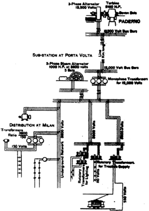 |
| Diagram of Distribution System at Paderno, Italy. Length of Line, 32 Km., No. of Wires, 18, Diameter of Wires, 9 Mm., Metallic Posts 60 Metres Apart. |
The line reaches Milan at the station of Porta Volta, where it is received on a suitable switchboard. From the switchboard the currents are conveyed to the transformer chamber. The transformers are supplied by the firm of Ganz & Co., are of the three-phase type and have a ratio of 12,000 to 3,600 volts. Their construction is quite simple. They consist of three columns of laminated iron disposed in one plane. On each column are wound a number of coils belonging alternating to the primary and the secondary circuit. This type is criticized by some from the point of view that not having the three magnetic circuits equally long it may give rise to a dissymmetry of the system. But the objection appears unfounded, and it is always possible in this case, where the transformers are numerous, to connect them in such a way as to compensate for the dissymmetry. The output of each transformer is 350 kilowatts, and its dimensions are: Height, 6.9 feet, 6.56 feet; width, 3.28 feet, and weight, 7,75 tons. The secondaries of these transformers are carried to a switchboard which forms part of the general switchboard of the station at Port Volta.
The works were commenced in February, 1896. Water was admitted to the canal in August, 1898, and the current was put on the line on September 28th. Public supply was given in Milan from Paderno on October 15th for the three-phase distribution and Edison network, and on October 29th for the traction service. The experience of a month or two is not enough to judge of the ultimate success of such a scheme, but it is highly satisfactory to know that the high-tension worked perfectly, the dynamos gave their guaranteed efficiency, and the line losses were exactly as calculated.
