[Trade Journal]
Publication: Electrical World and Engineer
New York, NY, United States
vol. 41, no. 5, p. 183-186, col. 1-2
26,000-Volt Installation at Grenoble, France.
By C. L. DE MURALT.
HIGH-TENSION plants are multiplying in Europe and one of the most interesting new installations of this kind is the plant of the Société Hydro-Eléctrique de Fure et Morge, near Grenoble, France, supplying electricity for power purposes to a number of factories situated in the valleys of the two rivers Fure and Morge, from which the company takes its name.
The water power is taken from the River Drac, a tributary of the Isère. It has a fall of about 21 ft. per mile and its flow varies from 7,000 cub. ft. at low water to 42,000 ft. at high water, but the mean flow is about 11,000 cub. ft.
Near the Pont de la Rivoire, about 11 miles from Grenoble, there is a stone dam across the river about 165 yards long. From there a canal of about 660 yards length brings the water to a reservoir with a total surface area of about 1,000 square yards and some 4 to 5 yards depth. This reservoir is divided into two compartments. The first one is destined to keep back the sand carried along by the water, and special openings are provided in the wall for periodically cleaning it and returning the sand to the river. An overflow separates the first from the second compartment, which is in direct communication with the conduit. The latter is built in the form of a tube, 130 inches in diameter and three miles long. The first 1 1/2 miles of the tube is made of armored concrete, while the remainder consists of a steel tube. The central station building covers a total area of about 1,200 square yards. It is situated about half a mile below the confluence of the Drac and of the Romanche and some 8 miles above Grenoble. The main machinery room is 48 yards long and 13 yards wide and amply lighted by a row of large windows. A crane of 15 tons capacity runs along the whole length of the building in order to facilitate repairs and inspections. In the basement immediately below the alternators there is a vaulted gallery containing the cables which connect the generators to the switchboard.
| |||
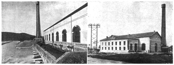
| Figs. 1 and 2. Outside Views of the Grenoble Power House. |
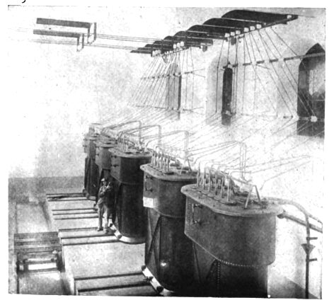
Next to the main room and at a somewhat lower level is the transformer room provided with a system of water pipes under pressure for the artificial cooling of the oil baths of the transformers. A small truck running on rails in front of the transformers allows the easy handling of the latter and their transportation to a special little repair shop placed at one end of the transformer room and provided with a 10-ton traveling crane.
Above this on the first floor is the switchboard in the center, the offices and store rooms to the right and the living rooms of the station superintendent to the left. All the foundations of the building are made of concrete and about 48,000 cubic feet of the latter have been used for this purpose.
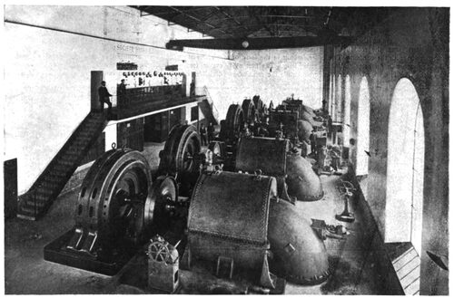
The station contains at present five turbo-alternators of 1,350 hp each, two turbo-exciters of 150 hp each and a small 5-hp turbine destined to provide the hydraulic pressure necessary for the turbine regulators. Figs. 1 and 2 show outside views of the power house, whilst Fig. 3 gives a good idea of the interior of the main machinery room. The turbines were supplied by Neyret-Brenier, of Grenoble. They are of the centripetal type with cylindrical distribution and they work with 15 feet of draft tube.
They are coupled with the alternators by means of elastic couplings. The speed of the turbines is 300 r.p.m., and they use something like 40 cubic feet of water per second when working under full load.
Three of the turbines have automatic regulators and are provided with compensating valves in such a manner that when the regulator shuts off water from the turbine it opens at the same time by a corresponding amount the compensating valve, thus keeping the quantity of water used by the turbine constant, the 40 cubic feet passing either through the turbine proper or through the opening in the compensating valve. The flow of the water in the pipes is therefore very regular.
The three-phase, alternating-current generators coupled to these turbines were furnished by Brown, Boveri & Co., of Baden, Switzerland. Each of the five alternators installed at present is capable of absorbing continually the 1,350 hp furnished by the corresponding turbine, and of developing 930 kw when working on inductive loads with a power factor equal to 0.8. They are designed for an e.m.f. of 3,000 volts at 300 r.p.m. and for a periodicity of 50 cycles per second. Transformers are used to raise this tension to 26,000 volts for distributing purposes.
The station has been arranged in such a manner that one generator forms, together with its transformer, a group normally indivisible, i. e., each alternator can under normal conditions only work with its own transformer. This arrangement has been chosen in order to simplify as much as possible the switchboard and all the connections, which is a very important point for any central station using high-tension currents. Besides, as there is always one entire group in reserve in this station, there is in this case no disadvantage connected with the arrangement just described.
The alternators are of the type with fixed armature and revolving interior field, the latter containing 20 poles, corresponding to 50 cycles for 300 r.p.m. The current for their excitation is furnished at 110 volts by separate exciters. The armature is carried by means of two feet on a cast-iron bedplate, which extends on both sides into the two main bearings. The high-tension winding is placed in completely closed tunnels punched into the armature core, and insulated from the iron by means of seamless micanite tubes which are tested before use under double the normal pressure.
Each generator has an output of 223 amperes per phase for cos ø = 0.8 and 180 amperes for cos ø = 1. The interior diameter of the armature is about 88 inches, the external diameter of the generator being about 135 inches. Each machine weighs about 30 tons.
Each of the two separate exciters is coupled to a 150-hp turbine and has an output of 100 kw. Each one can supply besides the energy necessary for the simultaneous excitation of the five alternators, all the energy needed for lighting the whole building and the switchboard. The other exciter is always kept in reserve.
These machines have four poles and a drum-wound armature with machine-wound coils placed in open slots. At 500 r.p.m. the The switchboard is divided into three principal parts, as follows r normal output of one machine is 870 amperes at 115 volts.
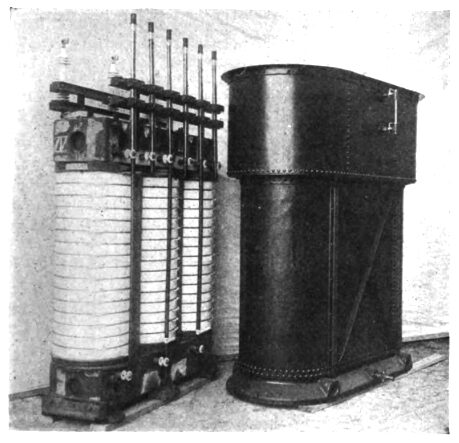
Each transformer is made up of three columns of sheet iron connected at bottom and top by two cross pieces. Each column is fitted with a series of high-tension and low-tension spools of cylindrical shape separated from one another by means of a vertical insulating cylinder. There are six high-tension and 16 low-tension tension spools, which subdivision of the windings has been chosen in order to facilitate repairs.
| |||
| Fig. 3. View of Interior Main Generator Room, Grenoble. |
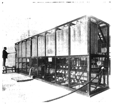
The whole transformer as described above is completely immersed in an oil bath formed of an elliptical iron tank, 75 x 30 inches filled with oil. The principal object of this oil bath is to ensure a more perfect cooling than would be the case with ordinary air-cooled transformers. In order to heighten the effect and to make the cooling still more efficient, a spiral water pipe is placed in the upper part of the tank and water is continually allowed to flow through this for cooling purposes. The transformers are of 1,150 kv-amp capacity each and their total height is about 8 ft. 4 in. The weight of one transformer including oil is about 9 tons.
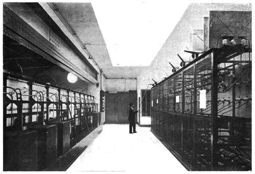
These transformers have been so arranged that by a simple change of connection, which can be effected at the switchboard, the ratio of transformation can be made to be at will either 3000/15000 or 3000/26000 volts. For this purpose they are provided with three low-tension and six high-tension terminals. The primaries are always connected in triangle; the secondaries are connected in triangle for 15,000 volts or in star for 26,000 volts between line wires. Fig. 4 shows one of the transformers with its oil tank. Fig. 5 gives a view of the interior of the transformer house.
One of the most delicate points of a high-tension central station lies in the difficulty of assuring an absolutely continuous service and at the same time perfect safety to the persons engaged in the station service. This naturally depends greatly on the kind of insulation used, but more perhaps on the general arrangement adopted for the different connections and switching apparatus. Brown, Boveri & Co. have long been known in Europe for their experience with high-tension work, and the way they have solved this problem in the present case is extremely interesting, as can be seen from the following description of the switchboard.
The switchboard is divided into three principle parts, as follows:
(a) The first one, which carries all the measuring instruments and from where all the different switching operations are effected, constitutes the switchboard proper. This part is mounted on a balcony on one of the long sides of the machinery hall, and as it is accessible to everybody it only contains such parts as carry low-tension current.
(b) The second part, containing the 3,000-volt switches and fuses, as well as the measuring transformers, is situated immediately below the first one between the floor and the balcony. Thus it was possible to chose an arrangement by which the switches can be operated by means of chain gear from the switchboard a.
(c) The third part is situated behind the switchboard a and on a floor on the same height with the balcony. This part contains the 26,000-volt switches and fuses, and, generally speaking, all the apparatus carrying the voltage of the transmission line.
The main switchboard, a, is composed of 11 panels, each of which is set apart for the instruments belonging to either an alternator, an exciter or an outgoing feeder; each panel is, therefore, provided with all the necessary ammeters, voltmeters, phase indicators and switches. Besides this, a central panel contains a totalizing voltmeter and a handle by which all the field rheostats can be operated simultaneously when coupled together, whilst each one of them can naturally also be operated singly by means of the handle placed on its own panel.
Each alternator panel contains a field switch. In addition, each of the two exciter panels contains one single-pole switch and one automatic minimum-current circuit-breaker destined to work when one exciter is substituted for the other one, thus avoiding a heavy breaking current if one of the exciters were to be cut out too early.
The board consists of an iron framework carrying all the connections and the rheostats for alternators and exciters and covered on its front side with slabs of white marble.
The 3,000-volt switchboard, b, carries the six-break main oil switches, the main fuses enclosed in removable porcelain tubes, and the current and tension transformers. This part also consists of an iron framework, which, however, is covered on all sides by wire netting in order to prevent any involuntary contact with parts carrying dangerous currents. As these nettings are made removeable, all the apparatus is easily accessible for inspection and repairs.
| |||
| Fig. 4. Transformer Cores and Oil Tank. |
The third part of the switchboard, c, is composed of nine panels, each corresponding either to a transformer or an outgoing feeder. This part contains the 26,000-volt fuses, separated each one from its neighbor by means of marble slabs in order to prevent a short circuit in case of breaking of one of the porcelain tubes and jumping of the arc formed by the blowing of the fuse. The 26,000-volt switches, also placed on this part of the board, are of the singlepole horn type. They are operated in groups of three, but are supposed to be used only after the main switch of the corresponding alternator has already been opened, i. e., under tension only, the current corresponding to the no-load current of the transformer, and therefore being negligible in quantity. The feeder panels contain also three measuring transformers for the three ammeters.
The totalizing panel contains, besides the measuring transformer for the totalizing voltmeter, an earth indicator by means of which the insulation of the transmission line can be ascertained at any moment, and in case of accident the line found which is grounded. Fig. 3 shows a front view of the switchboard. Figs. 6 and 7 show some of the details of its construction.
Excepting the connections between exciters and switchboards (870 amperes) and the 26,000-volt bus-bars (125 amperes), which are made of bare copper, all the connections between generators and switchboard, between switchboard and transformers, between transformers and 26,000-volt apparatus and from there to the outgoing lines, are made of cables with specially high insulation. They are supported in the galleries left in the basement by means of special insulators fixed to iron framework. The arrangement is such that inspection of all parts is easy and can take place without any danger at any moment.
Six holes are left in the wall of the building and fitted with earthenware tubes of a large diameter, erected with an inclination towards the outside. Concentric with these tubes are glass tubes of smaller diameter carried by the outgoing insulated wire itself and intended especially to prevent deterioration of the insulation at this exposed point.
Before leaving the building each line passes a lightning arrester which is of the single-pole horn type in connection with a water resistance and a fuse. As these lightning arresters are designed to work at 26,000 volts, the distance between the two horns is fixed at about 10 inches and the three arresters are so connected together that the current following an atmospheric discharge will have to traverse two such air gaps on its way from one line to the other besides encountering earth between the two gaps.
As a supplementary means of safety, auxiliary lightning arresters of the Wurts type are placed between each transformer and generator on the 3,000-volt circuit in order to protect more efficiently the alternators in case of an accident happening to the main lightning arresters.
A very complete set of tests has been made on these machines, first in the shops of Brown, Boveri & Co., and once more after their erection. We give below the figures obtained during the official tests made at the central station by the engineers of the Fure et Morge Company:
(1) Alternators of 1,350 hp each, 3,000 volts, 300 r.p.m., 50 cycles per second.
Efficiency at full load (cos ø = 1 ) 180 amp............................. 94.5%
" " " (cos ø = 0.8) 223 amp........................... 93.8%
" half " (cos ø = 0.8) 113 amp........................... 90.8%
The temperature rise after a continuous run of 6 hours at full load was found to be only 35° C.
The difference in potential between no load and full load for power factors varying between 1 and 0.7 was found to be:
For cos ø = 1...........................4.7%
For cos ø = 0.8....................... 13 %
For cos ø = 0.7........................ 15 %
The insulation was tested by applying 6,000 volts alternating current during 10 minutes between the windings and the frame.
Finally, the total load was suddenly taken off of an alternator running at full load, which caused the turbines to run away. Thus a speed of 515 r.p.m. was obtained and maintained for some time without causing any trouble whatever.
(2) Three-phase transformers, three columns in an oil bath with artificial cooling by running water, 1,150 kv-amp each, 3000/26000 volts.
Efficiency at full load, 925 kw (cos ø = 0.8).................. 97.8%
" half " 473 kw (cos ø = 0.8)..................... 97 %
" 1/4 " 236 kw (cos ø = 0.8)................... 95 %
From the curves taken during the tests at full load it was found that in order to keep the temperature of the oil bath at about 44° C. above that of the surrounding air, a quantity of 6 gallons of water per minute was sufficient, if the temperature of this water was about 5° C. at the entrance and 15° C. at the exit.
| |||
| Fig. 5. Interior of Transformer House. |
The same curves also showed that the transformers could work continuously during 45 hours without any cooling water at all, without any danger of an excessive rise in temperature, provided the temperature of the oil bath was not more than about 12° C. at the start.
The difference in potential between no-load and full load was found to be:
For cos ø = 1......................... 1.0%
For cos ø = 0.8...................... 4.5%
The insulation of the transformers was tested by applying a pressure of 60,000 volts alternating current between the high-tension windings and the frame and also between high and low tension windings.
(3) Exciters. 100 kw, 115 volts.
Efficiency at full load............. 92%
" half " .................... 89%
The greater part of the energy produced by the generators is used in the Département Isere in the industrial region northeast of Grenoble, in the valleys of the Fure and the Morge, the principal centers being Moirans, Voiron, Rives, Charavines, Fures-Tullins.
Moirans is about 22 miles from the central station, Voiron about 4 miles further in the valley of the Morge, Rives about 5 miles west of Moirans in the center of the valley of the Fure about half way between Charavines and Tullins.
The problem was, therefore, to transmit about 3,500 kw to Moirans, about 1,300 kw from there to Voiron and about 1,600 kv. to Rives for further distribution in the valley of the Fure.
| |||
| Fig. 6. View at Rear of Switchboard, Showing the High-Tension Section of Board. |
Twenty-six thousand volts was adopted for the transmission line, permitting of the use of six copper wires, each of 7 mm diameter, from the central station to Moirans, and three similar wires from there on in each of the two directions mentioned above. The six wires of the line from the power house to Moirans could readily be carried on ordinary wooden poles, but it so happens that this line is exactly parallel to the line of the Societe Grenobloise de Force et de Lumiere, which company also uses the Drac for power purposes, and the two companies, therefore, agreed to use common supports for their line wires. They chose poles of iron framework carrying at their upper end about 10 yards from the ground three wooden cross arms, the six insulators of one company being fastened to one side, and those of the other to the other side of these cross arms. These poles are placed at about 70 yards apart, and at the place where the line spans the Drac two specially strong poles are placed about 170 yards from one another. The two lines thus go together up to Moirans, where they separate and where the line of the Fure et Morge Society splits up and is carried from there on wooden impregnated poles.
Glass insulators of the Provo type are used and were furnished by the Hemingray Company, of Muncie, Ind. According to the general European custom, they are mounted on iron pins of what is usually called swan neck shape. The insulators have triple petticoats, and each insulator was tested before erection with a pressure of three times normal line voltage.
The fact of having the lines of two different companies on the same poles created the desire to be able to connect the two lines in such a way as to make use of one company's lines for the total load in case of an accident happening to the other line. Special coupling stations have been erected for this purpose at three different points, where a special set of switches allows of any desired connection being made.
According to the size of the customer's motors, a simple transformation from 26,000 volts down to 1,000 volts, or a double transformation from there down to 120 volts is used. The number of transforming stations has been reduced as much as possible, and there are only three types of transformers in use in order to be able to keep a complete set of reserves for cases of emergency. There are 11 stations with transformers of 500, 300 or 150 kw. The two larger types are designed for artificial water cooling, and are of the same type as the transformers in the central station. The 150-kw transformers are of the ordinary type in an oil bath.
The transformer houses are of masonry work and special windows are provided for getting at the primary and secondary fuses used in connection with these transformers. Lightning arresters are also provided for the incoming and outgoing lines, the high-tension arresters being of the horn type and placed outside on the poles, the low-tension arresters of the Wurts type being placed inside the sub-stations. In addition to this, each station is fitted with a 26,000-volt main switch, permitting of cutting off current from the transformer in case of inspection or repairs.
Besides these primary transformer stations, secondary transformers are used for those motors employing low-tension currents. These transformers are of the ordinary oil type in sizes of 100, 50 or 30 kw, and are usually placed on the customer's premises somewhere near the motor they are intended to serve. They are usually fitted with a set of primary and secondary fuses only without any lightning arresters.
All of the energy is used for power purposes and the company has not gone in for lighting work at all, as most of the towns traversed by its line have lighting plants of their own. The power is used for a great variety of purposes, the principal use being for the driving of paper mills, silk spinning and weaving mills, cotton and linen spinning and weaving mills, flour mills, mechanical work shops, oil mills, straw hat factories, iron and steel works, etc. Most of these need a very constant speed for driving their machinery, although they are often subject to great and sudden changes in load. The asynchronous motors thus presented a great advantage besides being capable of being handled by men not particularly trained for this class of work. The greater number of these motors are used for driving shafting by means of belts which were formerly driven by steam engines. The sizes of these motors vary between 1 hp and 120 hp.
It is interesting to note the conditions imposed by the Fure et Morge Society on its customers:
(a) All motors above 5 hp must have a wound rotor and be provided with a special starting rheostat.
(b) These motors shall not use more than normal full load current when starting.
(c) The power factor of these motors must be at least 0.85.
| |||
| Fig. 7-A Section of the Switchboard. |
The power is rented at the secondary terminals of the transformers in electric hp of 736 watts. The main object of the installation was from the beginning the providing of cheap power to the different industries of the region, and a special contract was therefore entered upon by the syndicated manufacturers of the district by which the Fure et Morge Society hands over its complete installation at the end of 30 years to the customers having signed a power contract for this period. Thus the company can count on a fixed yearly income and the prices for the power could be adjusted as follows:
150 francs per hp per year for use during 24 hours per day.
125 francs per hp per year for use during 12 hours per day.
As the cost of the hp per year furnished by steam engines had hitherto been from 200 to 400 francs, it is easily seen that this tariff meant a great reduction of manufacturing costs, and it will certainly go far towards developing further the industry of the region.
The installation was put into regular service March 1, 1902, and since then has been running continuously without incident. This power transmission shows the great development which this art has of late undergone in Europe, and though higher voltages have been successfully employed in the western part of the United States, yet the voltage used by the Fure et Morge Society is the highest used so far in Europe.
