[Trade Journal]
Publication: Street Railway Journal
New York, NY, United States
vol. 12, no. 8, p. 488-489, col. 2, 1
High Voltage Transmission Line.
The work on the pole line for the electric power transmission between Niagara Falls and Buffalo is being carried forward rapidly by the contractors, the White Crosby Company. In the city of Buffalo, among the first users of power will probably be the Buffalo Railway Company. Owing to the high voltage carried and the importance of keeping the line in good condition for use, the greatest care is being erection.
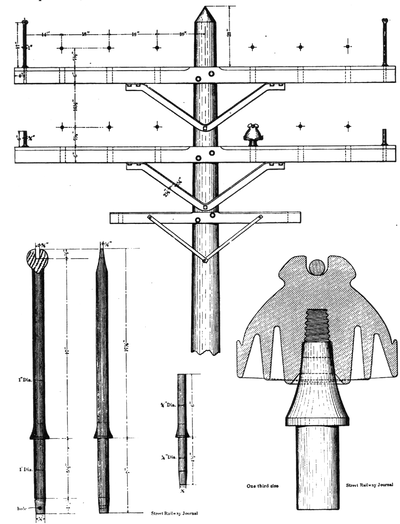 |
| Details of Niagara High Voltage Transmission Line. |
The pole line will extend for the greater part of the distance over the company's own right of way, which will be fenced in. The poles will be of cedar, circular in section, and in height from 35 ft. to 65 ft. above the ground. They will be set in the ground to a depth of from 7 ft. to 8 1/2 ft. In firm earth the poles will be set in the earth, which will be carefully tamped about the butts; in soft earth, the poles will be set in concrete. The distance between the poles on straight line will be 100 ft. The diameter of the poles at the top will be not less than 8 ins., and front this down it will gradually increase in diameter. At the ground line the 35 ft. pole will be 14 ins. in diameter and the 65 ft. pole 28 ins. in diameter. On curves the poles will be considerably heavier than those used on straight line.
Each pole will carry three cross arms, the upper two for the power wires and the lower for telephone wires. The power cross arms will be of heart pine 12 ft. in length, and 4 ins. x 6 ins. in cross section. They will be supported by steel angle braces 2 ½ ins. x 2 ins. x ¼ in. These braces will be in one piece to better keep their place and at curves braces will be used on both sides of the pole. Each brace is secured to the cross arm by four ½ in. lag bolts 4 ins. long, and to the pole by 1 ¾ in. lag bolts 5 ins. long.
The pins are of straight grained locust, of special shape so as to secure a good bearing for the insulation. The spindle is 2 ins. in diameter, and the pin at the shoulder, 3 ins. in diameter.
The insulators themselves are of special shape, with double petticoat to secure the best of insulation. The feeders are carried in a slot on the top of the insulator and are held in position by tie wires. There will however probably be little or no strain on these tie wires as the whole strain will come on the insulator itself. The insulator has also a skirt on each side to drain ally rain away from the cross arm, so far as may be possible.
A very novel feature in the pole line will be the provisions for lightning protection. The power wires will be guarded on each side by ordinary galvanized barbed fence wire which will be carried on pins shown on page 488 mounted at the extreme ends of each cross arm. An ingenious method of grounding these pins is provided by drilling in the lower end of each pin where it projects through the cross arms a hole through which a No. 6 copper wire can be strung. Each lower cross arm has also a shorter pin for guard purposes.
The third or lowest cross arm is of the standard six foot, six pin type.
