[Trade Journal]
Publication: American Electrician
New York, NY, United States
vol. 9, no. 6, p. 211-219, col. 1-2
ELECTRICITY AT NIAGARA FALLS
THE subject of this article is perhaps the most hackneyed in the entire range of periodical electrical literature; indeed, it would be difficult to find a commercial development in any branch of industry which has been more exhaustively described. In what follows, therefore, no attempt will be made to give the usual journalistic descriptions, but instead a brief and concise review will be presented of the present situation at Niagara with respect to electrical development, with particular reference to the newest applications and to details of operation.
Generation. -- There are two distinct enterprises of this nature at the Falls. First, that of the Niagara Falls Power Company, of which so much has been said and written; and, second, the Niagara Falls Hydraulic Power & Manufacturing Company's enterprise, of which comparatively little has been published, but which is by no means insignificant.
The Niagara Falls Power Company is to-day operating a plant of 15,000 HP, which comprises a portion of the 50,000 HP-plant originally designed and now being rapidly pushed to completion. The hydraulic arrangements are, with some slight modification, those proposed by Thomas Evershed, in 1843. His idea was to construct a short canal a mile or more above the Falls, which should feed a system of penstocks, the tail-water to be conducted through a tunnel discharging inconspicuously below the Falls. The amount of water deflected from the Falls by the utilization of 100,000 HP he estimated to be less than 4 per cent., which would reduce the thickness of the fall less than 2 ins.
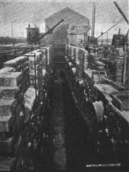
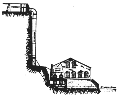
Inasmuch as there has been some outcry as to the danger to the natural beauty of the Falls involved in a large use of power, a few words may not be out of place. The ornamental caption of this article serves a purpose in this respect other than its more obvious one. It consists of a panoramic view of the Falls, in one corner of which is the tunnel outlet. A ready comparison of the volume of water deflected to the volume passing over the Falls may be made, and the most hypercritical guardian of the Falls cannot but admit, on noting this comparison, that any danger is only imaginary. The water level of the Falls varies quite markedly, and is made a matter of record at the power house by means of a suitable registering instrument. On the inspection of a number of such charts the writer found values ranging from an effective head of 137 ½ ft. to 135 ½ ft. The mean appeared to be about 136 ft. This variation is attributed to winds on the lake, high water being accompanied by a high west wind.
The Canal. -- The canal is about 178 ft. long and 12 ft. deep, and when utilized to its fullest extent will develop 100,000 HP. The company owns land on either side of the canal, and thus is at liberty to take water from either side. The gratings, which exclude foreign matter from the penstocks, are of iron. In the winter time, when anchor ice becomes troublesome, a boiler of about 100 HP is called into play. By means of flexible tubing the anchor ice is thawed loose from the grating by a jet of steam and hauled out by long rakes. The water is remarkably clean in summer, when little clearing of gates is necessary.
| |||
| Fig. 5.Excavating the New Wheel Pit. |
The Penstocks.There are ten of these, of which only three are now in use. Four lead to the present wheel pit, and six will supply the turbines which are to be in the new wheel pit, now in course of construction. The penstocks are 7 ½ ft. in diameter and taper down to this circular dimension from an elliptical section, the major axis of which is some 50 per cent larger. The penstock tubes are of steel, built into the masonry. A short rectangular fore-bay directs the water from canal into penstocks.
The Wheel Pit. -- This is a construction involving long and arduous labor. It is an excavation 30 ft. wide and 180 ft. deep, and sufficiently long to accommodate ten turbines.
| |||
| Fig. 6The Thrust Bearing. |
A better idea than conveyed by mere figures can be obtained by an inspection of Fig. 5. Here the new part of the wheel pit is shown, sunk to a depth of 140 ft, and with 40 ft. further yet to go.
It will be noted that the sides of the pit have a serrated appearance, like the clapboards on a house in an inverted position. This is the work of a grooving machine, which consists simply of a movable steam drill, having a lateral motion as well as one in the direction of its length. This grooving machine cuts a slot 6 to 8 ft. long instead of a hole, and the slot having been made to the depth of a foot and a half, the rock between is broken up and removed and a fresh start made.
The pit shown in the picture will, when complete, require the excavation of over 40,000 cubic yards of stone, at an approximate cost of $3 per cubic yard. It would be impossible to construct a pit of such depth in other than solid rock, on account of the difficulty of shoring the sides.
| |||
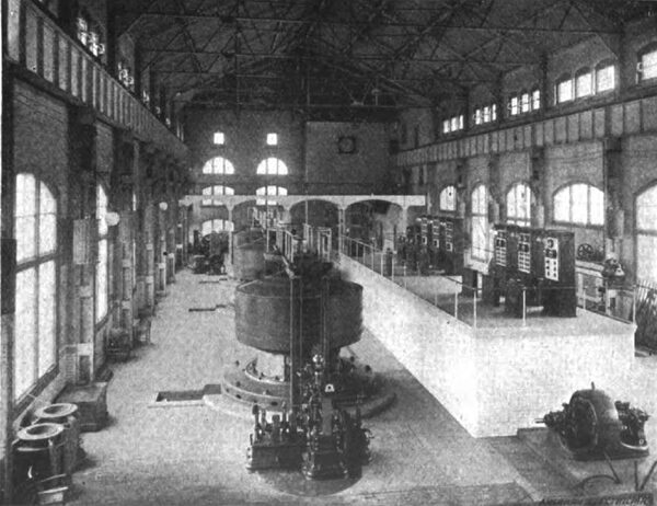
| Fig. 7General View of Niagara Falls Power Company's Generating Station. |
The Turbines.It is rather disappointing to the patriotic American engineer to be obliged to say that we were compelled to go abroad for the turbine design for this installation. The exceptional character of the work, and the fact that the designers, Messrs. Faesch & Piccard, Swiss engineers, had been successfully solving similar problems in their native country, must be the excuse.
The turbines are capable of delivering 5500 HP each, and are believed to have an efficiency of something over 70 per cent. They are fed by vertical flumes descending perpendicularly to the bottom of wheel pit.
The Tail Race.This consists of two tunnels, one a lateral tunnel at right angles to the other, or main tunnel, which leads to the river below the Falls. These tunnels have been so exhaustively described that a passing reference only is necessary.
The width of the main tunnel is 18 ft. and 10 ins. Its section is an ellipse, with its major axis vertical and flattened at its lower end, and having a section of 386 square ft. The height of the head of the tunnel above the lower river is 40 ft., and this incline produces a velocity of flow of 21 ft. per second, or a little less than 20 miles an hour. The length of the tunnel is 7000 ft., cut through the solid rock. In order to make a smooth raceway it is lined with bricks. It is of statistical interest to note that it required the removal of 300,000 tons of rock, and that 16,000,000 bricks were used in its construction.
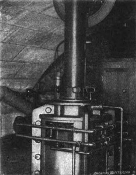
The Main Shaft.Having followed the course of the water to the end of its useful career, we now return to the turbines and trace the path of the power. The turbines deliver their power to a vertical shaft, which consists of a tube 38 ins. in diameter, with 3/4-in. walls. At the bearings the shaft becomes solid and reduces to 11 ins. In diameter. The thrust bearing, which prevents the shaft from lateral play, is very like a small thrust bearing on an ocean liner, except that it is vertical instead of horizontal. It is shown in Fig. 6. It is provided with a circulation both of water and oil, but the former is seldom, if ever, used, as the bearings run sufficiently cool with the latter. The thrust of the shaft is minimized by the fact that the upward thrust of the turbines is largely balanced by the weight of the revolving system. It is interesting to note that all of the bearings that are thus fed have the bulb of a thermometer placed in the circulating oil.
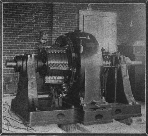
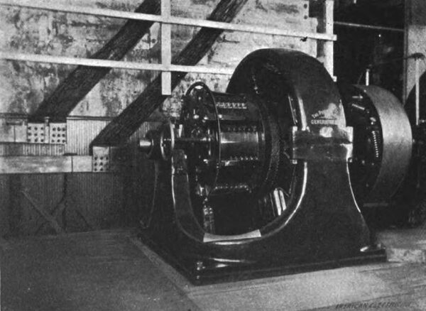
The Dynamos.These are probably the most interesting machines of their class in the world, but for reasons already given, an exhaustive description at the present time would be superfluous.
A cylindrical stationary armature wound with two distinct distributed windings is surrounded by a revolving steel ring, carrying twelve inwardly-projecting pole pieces. This ring is suspended from and revolved by a circular plate, which is keyed on to the vertical shaft, the combination of the last two members being suggestive of a gigantic steel mushroom, of which the shaft forms the stalk.
The output of the generator is delivered to four wires forming two circuits, and passes to the switchboard. The exciting current, which varies from 45 to 90 amperes, according to the load, is led in at the top of the machine by two slip rings, which are the only sliding contacts on the dynamo. The speed of the machines is 250 r. p. m., and the number of cycles per second is practically 25. The working voltage is 2000-2200, at which pressure each machine can deliver two currents of 850 amperes, each differing by 90° in phase. One of the generators is the subject of Fig. 3. When in motion the draught created by the fan-shaped projections on the upper part of the machine is so great that it is difficult to manipulate a camera in its vicinity. The losses of the dynamos, while a very small percentage of the total output, are nevertheless of considerable horsepower, and require ample ventilation to dissipate them, but the above arrangement proves more than adequate.
The Governors.These are also of the design of Messrs. Faech & Piccard, and in the foreground of Fig. 3 one of them may be seen. A centrifugal governor controls a set of pawls on an oscillating member and causes one or the other to engage with a ratchet, which operates the gates. The device of a nest of epicyclic-bevel gears is utilized to secure a prompt action.
A most interesting feature of the governing of this station is the fact that though each turbine has a governor, only one governor is effective. The alternators run in multiple, and therefore synchronously. Thus, if a governor adjusts the speed of a wheel higher than that of its mates, all the other machines must come to that speed regardless of the dictation of their governors. Therefore, the governor that is set to regulate to the highest speed, will operate, and the others will be idle. Inasmuch as it is impossible to set two governors to regulate exactly alike, there will always be one of higher speed than any of its fellows, and will deprive them of their control over their machines. The governors operate by controlling numerous gates surrounding the turbines.
| |||
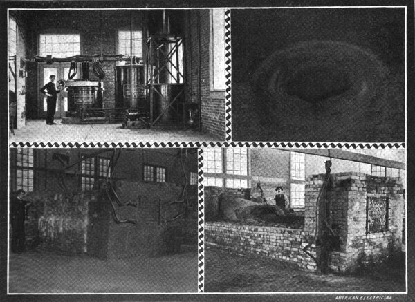
| Fig. 8.Transformer and Regulator.: Fig. 10.Section of Furnace.: Fig. 9. Furnace at Work.: Fig. 11.Furnace Dismantled. Details of Plant of Carborundum Company. |
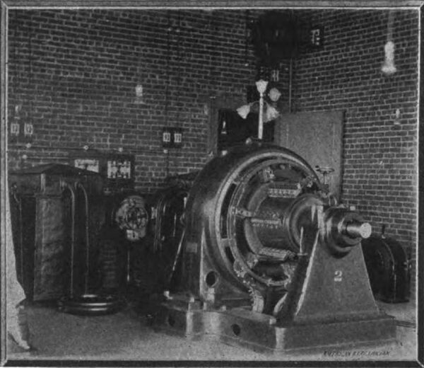
The Control.An elevated platform contains the switches, and on the top of the platform are the devices controlling them. The switches, which are, of course, very large, are manipulated by compressed air.
There are two complete sets of bus-bars, and any machine, or any circuit, can be switched on to either, or disconnected altogether. The field switches are arranged so that the circuit can be opened through a resistance, which provides a path for the discharge. Each machine has a panel carrying the following instruments:
Synchronoscope, two ammeters, two voltmeters and two wattmeters, or one of each of the latter for each of the two-phased circuits, one direct-current ammeter for measuring the exciting current.
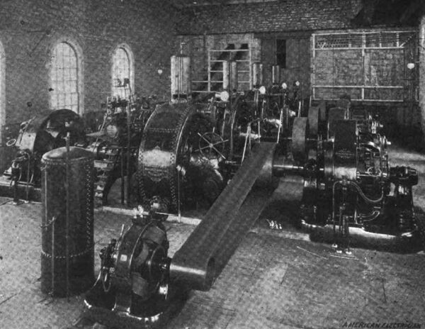
In Fig. 2 is a view of the switching platform, in which one of the measuring panels and the pedestals containing the controlling levers can be seen. Fig. 7 shows a general view of the station.
The Building.The building is a work of architectural beauty, as well as of utility. It is of limestone, and has an imposing front, while a well-kept lawn surrounds a paved court-yard. A bronze pedestal in the center of the circular yard is surmounted by a flag-pole. The machinery hall is a plain pitch-roof structure traversed by a Sellers crane. The design is such that the building may be readily extended to cover the remaining ten wheel pits without marring its symmetry. The building occupies one side of the canal, which is spanned by a conduit and hallway for the mains passing to the transformer house, which is the center of ramification of the various lines. This house is also built to harmonize with its surroundings.
| |||
| Fig. 12Rotary Converter Without Field Winding. |
| |||
| Fig. 13Rotary Converter With Field Winding. |
| |||
| Fig. 14Station of Buffalo-Niagara Falls Electric Light and Power Company. |
The Distribution. -- The power from this installation is distributed as follows: The Pittsburg Reduction Company takes 3500 HP, from which it realizes 3000 HP in direct current by means of static and rotary transformers.
The Carborundum Company uses 1000 HP, which it reduces in a static transformer to a pressure which can be varied from 250 to 90 volts.
The Acetylene Light, Heat and Power Company was using 1000 HP, transformed to current at 100 volts pressure. It has recently shut down to increase the plant capacity, and will shortly start up again, using 5000 HP.
The Niagara Electro-Chemical Company is using 400 HP, transformed to direct current at 160 volts. The plant has a capacity of 1000 HP.
The Central Power & Conduit Company uses 1000 HP, which is stepped up in the transformer house to 11,000 volts, and at that pressure transmitted to Buffalo. There it is stepped down and transformed to direct current at 550 volts.
The Buffalo & Niagara Falls Electric Light & Power Company uses 500 HP of alternating current for lighting the city of Niagara Falls, and 150 HP of direct current for arc lighting.
The Niagara Falls Water Works Company uses 45 HP of direct current at 500 volts, and the Hygeia Ice Company 50 HP at the same pressure. These last two customers are supplied from a bank of rotary transformers at the power house. Figs. 1 and 4 shows two types of rotary converters which are used in this bank, representing respectively the Westinghouse and General Electric Companies.
The prospective users of power are as follows: The Mathiesen Alkali Works, which have just been completed, and in which about 2000 HP will be used; the Albright-Wilson Company will use 200 HP, the Chemical Construction Company will employ 500 HP in producing its goods, and about 500 HP will be used for elevating grain in the city of Buffalo.
| |||
| Fig. 15Plant of Niagara Falls Hydraulic Power & Manufacturing Company. |
General Manipulation.In such a plant as this it is not necessary to observe the rules of economical loading of machines, for the reason that whatever power is not used from the turbines will pass over the Falls, and nothing will be saved. It is, therefore, better to load each machine as lightly as possible, for durability's sake, for, of course, a heavily-loaded machine gets more wear and tear. As a matter of fact, however, the way the load is distributed makes but little difference, as convenience is the principal dictator as to what machines shall run and what shall not.
The power is distributed to the customers, and as it is mostly used for electric furnaces and similar devices, therefore it by no means follows that the two circuits of each machine will be balanced. As to motors, the higher cost of polyphased apparatus has created a general preference for direct current motors, which are operated directly from the circuits of the rotary transformers at the station.
The machines are thrown in multiple by means of a Westinghouse synchronoscope, which is a little magnetic affair, the moving parts of which are acted upon by two magnets, one on the secondary circuit of each generator, in such a manner that when the machines are in step the magnetizing influence will be balanced and no deflection of the indicating needle will occur; at this moment the machines may be thrown in multiple, after which it is a practical impossibility to get them out of step.
| |||
| Fig. 16General View of Generating Room of Niagara Falls Hydraulic Power & Manufacturing Company. |
The excitation of the generator is accomplished by means of a small rotary transformer driven from the two-phased circuits. The station would be in rather an awkward predicament if everything should shut down, were it not for the fact that a small dynamo in an adjacent building is available as a starter, and once started the plant again becomes independent. The proposed installation of four exciters with a separate turbine will do away with any such necessity.
The half-hourly record which is made on the log book comprises the watts, the volts and the amperes of each of the two-phased circuits, the temperature of the bearings, the exciting current and other important data. The water level is automatically registered and measured. The field circuit on the machines is provided with a special switch, by means of which the discharge takes place through a resistance, and is thus prevented from puncturing the insulation or causing a bad arc at the switch. The feeders are provided with derived circuits which actuate the recording wattmeters, and therefore each customer pays for his own line loss.
The Carborundum Company.This company takes power from the Niagara Falls Power Company to the extent of 1000 HP. This is received in a transformer, which converts it from 2200 volts to a pressure of 250 volts, and by means of an enormous reactive coil the latter can be controlled from the maximum down to 90 volts. These two large pieces of apparatus are shown in Fig. 8, and their great size will at once be noted. The losses of these machines are extremely small in proportion to their output, but their great size makes the actual amount of horse-power wasted quite large and sufficient to cause considerable annoyance by heat, were it not that oil is continuously circulated in both members by a little pump.
Two massive bus-bars carry the current to the furnace room, where it is used in the manufacture of carborundum. This material is a silicate of carbon, and is extremely hard, much harder than any substance except the diamond. It is produced by subjecting its constituents to an enormous heat, in what is known as an incandescent furnace. Such a furnace is shown in Fig. 11. The ends contain each a bunch of 60 carbon rods 30 ins. long and 3 ins. in diameter; the ends of these rods are each drilled with a little hole, carrying a plug, which is a portion of the large bronze plate to which the cables are attached. Two such terminals are placed in either end of the furnace, which is then built up of loose brick, no mortar being used.
The mixture which unites with coke to form carborundum, consists of salt, sawdust and glass sand, mixed in certain proportions. The furnace is filled rather more than half full of this mixture. A semi-circular trench is then hollowed out, the axis of which coincides with a line drawn between the centers of the terminals in either end of the furnace. A core of coke, which is cylindrical in section, is built in and bridges the space between the two terminals. Each furnace requires about 1100 lbs. of new corethat is, fresh cokeor 850 lbs. of core which has already been used in a furnace. A complete cylinder is about 21 ins. in diameter and 14 ft. long. Substantial contact is made with the carbon terminals by packing the coke tightly in among the rods previously mentioned. The core being complete, the mixture of sawdust, salt and sand is thrown into the furnace and heaped high above it, the total height being about 8 ft. The furnace is then ready for the electric current.
The current is applied at the maximum voltage at first; if the furnace has been built with new core the amount of current taken is quite small at first, but if old core has been used it almost immediately reaches a value of 1,200 amperes, due to the greater conductivity. The voltage is then increased until a sufficient current flows to make the core quite hot, and as it heats its resistance diminishes, so that finally the voltage has to be reduced. Presently the furnace resistance becomes a fairly constant quantity, and having once adjusted the current to the proper value, further regulation is usually unnecessary. For about an hour no apparent change is noticeable in the furnace, but after a certain time gaseous products begin to ooze out from between the bricks and take fire.
About 5 ½ tons of gas are given off during the reaction. Fig. 10 shows such a furnace at work, and also serves to give an idea of its construction. At the end of 4 or 5 hours the top of the furnace begins to gradually subside and cracks open on its surface, from which pour out flames tinged yellow by the sodium contained in the salt. If the furnace has not been built up in a very porous shape it is liable to explode at this juncture, scattering large amounts of the mixture in all directions.
A fissure will sometimes suddenly open in the top of the furnace and a roaring pillar of flame several feet high arise; and it is then necessary to cut off the current altogether and allow the furnace to cool. The mixture is then removed to a depth of about 2 ft., and the blow-hole is removed and the cavity filled up with fresh mixture.
The sawdust is added to the mixture for the purpose of avoiding this "blowing," as it is termed by the workmen.
At the end of about 24 hours the process is completed, and the furnace is allowed to cool, which takes several hours. Then the sidewalls are taken down and the outer unchanged mixture is removed, thus exposing around the core an outer crust of amorphous carborundum. This crust can be easily peeled off from the inner crust, which is also amorphous carborundum, but in a more powdered form. This is removed with a spade, and the crystalline carborundum surrounding the core is next exposed. This is a most beautiful compound, and wherever there is a hollow and the crystals have had opportunity to form they are remarkably large, sometimes measuring ½ in. on the side.
A section of the furnace (See Fig. 10) shows first a crystalline core of carborundum; second, a surrounding mass of amorphous carborundum in a light greenish powder, and third, the crust of amorphous carborundum. The dividing line between this crust and the unchanged mixture is very abrupt. Mixed in with the core is some carbon in a graphitic form. The amount of graphite depends upon the temperature at which the furnace is operated, and too high a temperature produces it in considerable quantity. The crystals of carborundum are broken up fine, washed in diluted acid to remove their impurities, sifted through sieves of various finenesses and sorted in bins, according to the number of meshes in the sieve. They are subsequently moulded with a suitable binding material into wheels, slips, rods and polishing paper and similar tools and materials for grinding. The substance is so hard that it is said to do many times the work of either emery or carborundum, and though more expensive than either, is largely used in preference.
| |||
| Fig. 17Generator, Pittsburg Reduction Company. |
The Pittsburg Reduction Company. -- This company has two plants at the Falls, one of which receives its power from the Niagara Falls Power Company, and the other from the Niagara Hydraulic Power & Manufacturing Company. That of the former company is located a short distance from the power house and consumes about 3500 HP, delivered at the power house end of the line, and 3000 HP is available in direct current at the terminals of the rotary transformers.
This current is used in producing aluminum from its oxide. A carbon-lined retort in which a carbon pencil is suspended forms the apparatus in which the reaction takes place, the retort itself and the suspended pencil forming the electrodes. The current is usually at a pressure of about 160 volts, and 60 retorts are placed in series. The aluminum oxide, combined with a suitable flux, is placed in the retort, and the combination of immense heat and electrolytic action causes the aluminum to be reduced from the mixture. This reduction by means of carbon is a popular method in use for reducing all metals, but it does not take place in the case of aluminum except at this enormously high temperature. The static transformers each receive current from the line, transforming from 2200 to 115 volts, and on passing through the rotary converter the issuing direct current has a pressure of 160 volts. The joint capacity of the converters is about 10,000 amperes.
The Niagara Electro-Chemical Company. This company uses about 400 HP in direct current at 160 volts. Its total capacity in rotary converters is 750 KW, comprised in three machines of 250 KW each. The static transformers receive current at 2200 volts and step it down to 115 volts, which the rotary transformers raise it to 160 volts, then transform it to direct current.
| |||
| Fig. 18Turbine and Governor. |
The rotary converters are of two types, one of the ordinary design with wound pole pieces, and the other of the induction type, the pole pieces of which carry no windings. A rotary converter, it will be remembered, does not depend upon the strength of its field for the control of its voltage, and it is really more of a commutator than a dynamotor. The effect of the strengthening the field of a rotary converter is a condenser effect on the line which compensates for the inductive drop, and can even produce a leading current, which is sometimes desirable. The converter which works without field windings has the advantage of being somewhat easier to start and is cheaper to manufacture, although it is but justice to say that the other converter can be started in exactly the same way by simply opening its field circuit. This induction converter is said to be the first to be commercially used.
The induction converter is started by interposing a choke coil in the two-phased circuits in the armature. As the surrounding pole pieces have no polarity, there is no need of waiting to obtain synchronism, for in the endeavor to complete the magnetic circuits of its armature the latter will revolve. The other converter can be started up in the same way, but when a synchronous speed is attained it is necessary to be careful to throw in the field circuit so connected that the armature flux and the field flux will work harmoniously. Figs. 12 and 13 show two types of converter used at this installation.
Current is used in this plant almost entirely for the manufacture of sodium, which is electrolytically produced by the decomposition of sodium hydroxide, or ordinary caustic soda. Thirty electrolyzing pots are used in series. Sodium is produced in these works not so much for sale as for use in manufacturing other reagents. Among these is peroxide of sodium, which is largely replacing peroxide of hydrogen as a bleaching agent.
The Acetylene Light, Heat & Pozver Company.The progress of this company will be of more than usual interest to electric light engineers, and thanks to the management some very interesting data have been furnished. As is well known, acetylene is a gas produced by the combination of carbide calcium and water, and is used for lighting houses, heating and power in the same way that ordinary illuminating gas is used. As the claims of its manufacturers have been widely spread, and the foundations for them have been fully detailed on this part of the subject we will not dwell.
The problem of the manufacture of its essential component, carbide of calcium, as a commercial article, and at commercial prices, is the principal object of interest. The plant of this company had been operating for some time, consuming about 1000 HP, but it has been largely increased, and 5000 HP will be shortly available. This power is transformed in five 1000 HP transformers, three of which are of the General Electric make, and the remaining two are Westinghouse products. They receive current at 2200 volts and transform to 100 volts.
It has been customary to use a choke coil on the secondary circuit, but it is found that this is not necessary, and that the current can be amply regulated by varying the distance between the terminals in the arc furnace.
This furnace is an interesting affair. A little alcove is built in a brick structure into which a little truck is run, the bottom of which is of iron and removable. A heavy iron lug is cast on one end of the truck, and when it is run in place in the alcove it is securely bolted to the corresponding plate, which is connected to one terminal of the transformers. The top sides of the truck are of sheet iron.
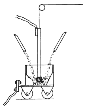
In the center of this truck is hung a large carbon rod, which is suspended from a wire rope, passing over pulleys to the controlling room. A diagram of this furnace is shown in Fig. 19. This carbon rod, which is of the most liberal dimensions, is lowered into the iron receptacle until it touches the bottom, and is then drawn away, pulling an arc after it, which carries 2500 amperes at 100 volts. This arc is often 13 ins. long, and the frequency of alternation is so low that it produces a deafening roar. Little chutes are then opened on either side of the truck and the component mixture falls down into it, and is subjected to the heat of the arc.
This mixture consists of ground coke and lime in the ratio of about 40 to 60 per cent., respectively. When subjected to the influence of the arc a button of calcium carbide quickly forms on the bottom of the truck, and gradually increases into an ingot, the carbon rod being drawn up as the button increases in size, until the truck is full. This ingot weighs about 700 lbs., and is surrounded by about 2 ft. of unchanged mixture, which is taken out, sifted and sent back to the conveyors which supply the furnaces. These conveyors and the other machinery about the works are driven by two two-phased, 75-HP General Electric motors.
The carbide is broken into small lumps and packed in iron drums, which hold about 500 kilos., and in 100, 50 and 10-lb. packages.
The time for forming an ingot takes from five to seven hours, according to the amount of current used. The regulation of current for each furnace is accomplished entirely in the regulating room, and the operator never sees the furnace itself; he simply adjusts the current to the constant value by raising or lowering the carbon rod, and he has the ammeter before him for guidance.
The alternating currents which are used are of such great volume that the inductive drop on even these short lines is very important and of no inconsiderable magnitude. For this reason the leads are of heavy flat strips and are interlaced; that is, alternate positive and negative leads are placed in a common bunch, passing upward to the bus bars, and this interlacing construction is carried as far as the furnace. It is noteworthy that this industry has been built up in nine months, and that these extensive works have been constructed in very much less time. The president of this company, Mr. C. C. Adams, and the treasurer, Mr. Edw. C. Naphyes, are largely responsible for the commercial success of the product so far, and to Mr. Jos. P. Devine, the manager, is due the credit of having modeled the works and directed their management in such a way as to produce calcium carbide as a commercial commodity.
 |
| Fig. 19.Diagram of Carbide Furnace. |
The Niagara-Buffalo Transmission.The length of this line is 27 miles, and over it is transmitted about 1000 HP at a voltage of 11,000. On all but about 4000 ft. the power is transmitted over bare wires, mounted on heavy porcelain triple-petticoat insulators. These insulators dependfor their dielectric properties largely upon the excellent quality of the procelain of which they are made. Each insulator weighs something over 12 lbs. It is provided with gutters on the outer petticoat to deflect the water, so as not to drip on the cross-arm. A great deal of trouble was experienced in obtaining the proper insulator for use in this work, and the one just described was finally selected after many others had been tried and failed. The successful product was that of the Imperial Porcelain Works, of Trenton, N. J., and they are entitled to no little credit for the complete satisfaction that their insulators have given in service.
The power is stepped up by a Scott transformer system, and converted from two currents, at 90° apart, to three currents, with 120° difference of phase, and is so transmitted to Buffalo over three wires, each of which has a cross-section of 350,000 CM. It is composed of nineteen No. 8 wires. The line is run on poles about 100 ft. apart, and each pole is stenciled "dangerous," as indeed it would be should one of the insulators upon it get broken, but under ordinary circumstances it is perfectly safe. The inductive drop is about 10 per cent. The last 4000 ft. of line consists of lead-covered cables, which are run along the edge of Erie Canal in board troughs. The repairs which are now being made on the canal, and frequent cavings along the edge have done much to interrupt the service, but these difficulties have been so marvelously well met by the high insulation of the line that its performance must be considered as a very creditable one, and plainly shows that transmission at double the voltage is a practical possibility. Indeed, it is contemplated doubling the working voltage in the near future, and the transformers are so wound that a change in connections will be all that is necessary to do this.
The power is stepped down by static transformers, and then through rotary transformers is converted into 500-voIt direct current, and used on the Buffalo Street Railway lines. Over this line, when complete, it is proposed to transmit much more power for local purposes about the city of Buffalo, but the constant annoyance that has been experienced by disturbances of the lead-covered cable system have made the Central Power & Conduit Company, which operates the line, rather loath to contract for power until it can guarantee a more uninterrupted service.
 |
| Fig. 20.Cross Section of Power House of Niagara Falls Hydraulic Power A Manufacturing Company. |
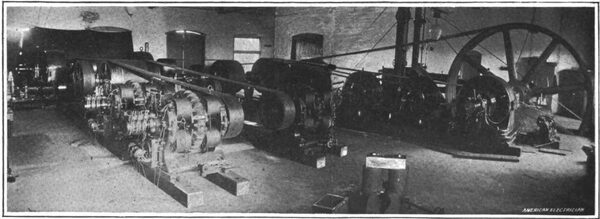
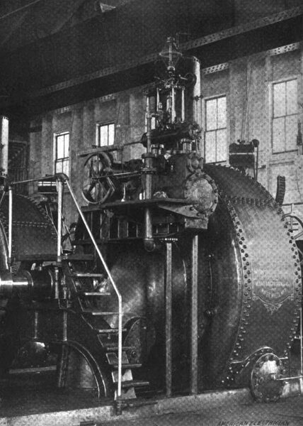
The Buffalo-Niagara Falls Electric Light & Power Company.This company operates two stations, the first of which, shown in general view in Fig. 14, was the original lighting station of Niagara Falls city, and formerly run by steam, the original engine showing in the right of the picture. It is now replaced by two two-phased induction motors of 300 HP each, operated from the Niagara Falls power station. These motors, which run at a speed of 500 revolutions per minute, drive a jack-shaft, which is divided into two parts by a friction clutch, and from this shaft are driven three alternators and three 125-light Brush arc dynamos. It may be asked why the alternating power is not used directly from the Niagara Company's mains, and the losses of transformation thus saved. But the transformer plant of this company, being built for 15,000 alternations per minute, is entirely unsuitable for the 25-cycle current, and the extreme cheapness of power will render the amount of saving so small that the large first cost obtained by the necessary change to use 25-cycle current direct would not be justified. The operation of this plant has been very continuous, and since the motors were installed it has never been necessary to use the engine.
Another branch of this plant is installed in the building of the Cliff Paper Company, which is located on the brink of the precipice, abutting the lower river, and consists of two monocyclic generators directly driven by a turbine supplied from the hydraulic canal of the Niagara Falls Hydraulic Power & Manufacturing Company. Although somewhat limited as to space, the plant is well arranged, and is a thoroughly modern installation.
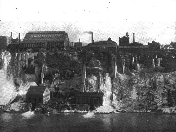
The Niagara Falls Hydraulic Power & Manufacturing Company.This company is a powerful rival of the Niagara Falls Power Company, and though but little has been heard of it, it possesses an extremely interesting plant, which has been constructed under plans representing the very highest engineering talent. The power is received from what is known as the hydraulic canal, which is 100 ft. wide, 18 ft. deep, and reaches from above the Falls to a place on the precipice below them, adjoining the works of the Cliff Paper Company. This canal is of many years' standing, and from it various taps have been made, supplying small industries in the locality with power. The general view of the precipice, given in Fig. 16, shows the sluices of these various plants to good advantage, and most of them, it will be noticed, utilize but a very small fraction of the total head available.
The principal industry utilizing this canal, and which is the subject of this section, gets its power from a fore-bay, which leads into a penstock 7 ft. in diameter and. descending to the foot of the precipice, feeds four turbines in the power house at the base under a head of 210 ft. This arrangement is shown in cross-section in Fig. 20. The pressure in the penstock at the base is about 85 lbs. to the square inch, and to resist this pressure %"-mild steel is used in this construction. The joints are doubleriveted lap joints, and the penstock as a whole is built with even more care than a well-made tubular boiler. As a precautionary measure, each turbine is supplied with a liberal air chamber, and there is a large air chamber at the end of the penstock (Fig. 16), which may be seen in the general view; a number of safety valves complete the safety device. The pressure in the penstock is used to manipulate the gates that shut down the water-wheels, and to move the piston of the governor gates.
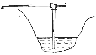 |
| Fig. 21.Hydraulic Injector. |
The turbines were manufactured by the James Leffel Company, of Springfield, O., and it is gratifying to note that in this case the designers did not deem it necessary to go abroad for turbines to operate under an even greater head than those of the Niagara Falls Power Company. On each end of the shaft of these four turbines is a direct-current generator, making eight generators in all. Six of these machines are used to generate current at 300 volts for the Pittsburg Reduction Company. The turbines driving the Pittsburg Reduction Company's machines are of 1700 HP, and the remaining turbines are of 1900 HP, in each case with threefourth gate, and it can be easily seen that the turbines could be forced to a greater power, as a matter of fact, to a maximum of 2000 and 2500, respectively. The current of the Reduction Company's machines, which, by the way, are of the Westinghouse make, is delivered to two enormous busbars, and transmitted up the precipice by two cables, each consisting of 250 No. 000 aluminum wires. These cables pass up a wooden-wire tower to the works of the Pittsburg Reduction Company, on the brink of the precipice. One of the machines of the Pittsburg Reduction Company is shown in Fig. 17, and a view of the bus-bars and the wire cables can also be seen in the same engraving.
The speed of all of the machines is about 300 revolutions per minute. The Pittsburg machines are governed entirely by hand; the field rheostats are not touched, but the opening of the wheel gate is varied by a lever. The machines are thus governed in pairs, and each must be adjusted to equality. The fourth turbine generator, of 500 volts pressure and 560 KW, is of the General Electric make. The speed is controlled by a Lombard water-wheel governor, which adjusts the speed within 2 per cent. See Fig. 18. One of these generators supplies railway current to the Gorge Road (200-500 HP), and to the Lewiston & Youngstown road (70-200 HP); on the latter road the maximum transmission distance is 16 miles. The other 500volt generator supplies a metallic circuit with about 300 HP for local purposes. On the feeders on the Youngstown road is placed a booster which will boost the voltage to a maximum of 250 volts, the machine being belted to the turbine shaft, as shown in the foreground of Fig. 16, which is a general view of the station. The station is a substantial building, without pretensions to anything but utility. It is spanned by a 100-ft. crane.
An addition to this plant has been for a long time contemplated, and is now being actually installed. It will contain five turbines of 2000 HP each, arranged in a similar way and adjacent to the present plant.
It is interesting to note how the energy of the hydraulic canal is being compelled to construct its own station. Compressed air supplied by compressors operated by turbines, provide the drills and channelers with motive power. The hoisting is all done with hydraulic power as the prime mover. An ingenious injector pump, shown in Fig. 21, serves to keep the excavation free from water. Pressure from the flume is supplied to the pipe A, and by its injector-like action forces the water up and out through the nozzle D.
The new flume to supply these five turbines is to be II ft. in diameter, and is to be built of 1 1/4-in. steel. It is expected that the machines will be three-phase alternators, but what is to be done with this 10,000 UP is not generally known. However, it is not to be assumed that a management which has thus far shown such marked commercial ability is going to increase the capacity of its plant with any chance of a considerable portion of it remaining idle.
