[Trade Journal]
Publication: American Machinist
New York, NY, United States
vol. 39, no. 5, p. 173-175, col. 1-2
The Manufacture of Porcelain Parts
BY ROBERT MAWSON
SYNOPSISThe dies shown comprise some of the simpler forms and others more complicated. The dies are single and double acting; various forms of ejectors are shown find described. The molding machine and manner in, wh ich it is operated lo produce these porcelain pails is shown, and the process is described.
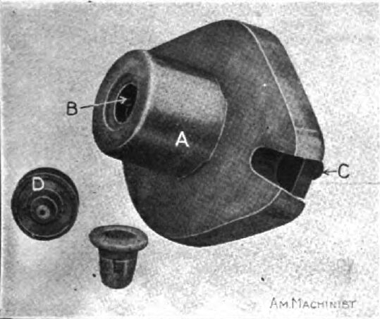
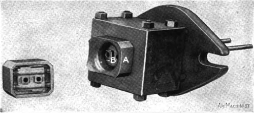
The making of porcelain parts for electrical and similar work is one of interest. Some of the dies and the method of using them are here described. The dies shown were made at the Mycock Machine Co., Trenton, N. J., and are shown in use at the Electrical Porcelain & Manufacturing Co., of the same city. The dies in Fig. 1 are of about the simplest kind and are for making a porcelain pipe howl. The female die A is fastened on the table of the machine, the core B and ejector being operated by a rod attached to the plate C. The male die D is fastened to the plunger of the molding machine and forms the inside of the bowl. One of the finished bowls is shown at E.
| |||
| Fig. 1. Pipe Bowl Dies |
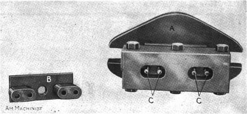 |
| Fig. 2. Dies for Sadiron Insulators |
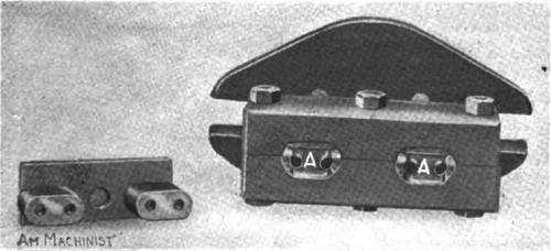 |
| Fig. 3. Dies With Ejector Blocks Out |
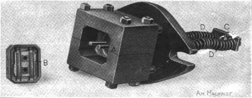 |
| Fig. 4. Dies for \"Condulet\" Receptacle Cap |
 |
| Fig. 5. Dies With the Ejector Blocks Forced Out |
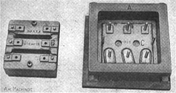
Fig. 2 shows the dies used for making the insulator block for heating irons and similar apparatus. The female die .1 is fastened on the table of the machine and the male die B is carried by the screw press in a manner similar to that described for Fig. 1. The core pins C are fastened into the female die. The die Fig. 2 is shown with the ejector blocks forced out in Fig. 3. After the dies have formed the piece the operator by means of a lever attached to a bar to which the ejector blocks A are fastened, forces out the finished molded part.
Notice should be called to the sharp corners through which the round cores in the ejector block pass. This is necessary so that the insulator block shall have a generous radius for the hole through which the current wire passes to prevent abrasion of the insulation.
DOUBLE-ACTING DIES
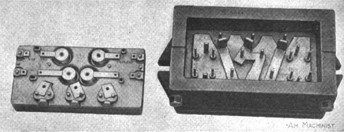
The dies used for making a Norbitt "Condulet" receptacle cap are shown in Fig. 4. These are fastened in a manner similar to those already described, A being the female and B the male die. The plate C operates the ejector mechanism by means of the two rods D, tension springs tending to keep the ejector block back in the female die. The part after being molded is ejected by a double motion, the square block which carries the finished piece being first ejected by the rods and coming to a stop. Further motion of the rods pushes up a round disk placed inside the square ejector block, thus forcing the finished part out of the die.
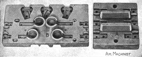
Fig. 5 shows the dies with the ejector blocks forced out, A being the square block, which is first operated upon, and B the round block which forces the finished molded part from the die. Fig. 6 shows complete the part made in the dies Figs. 4 and 5.
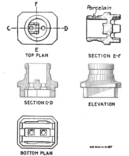 |
| Fig. 6. Cap for Norbitt \"Condulet\" Receptacle |
 |
| Fig. 7 Dies for Pony Snapswitch |
 |
| Fig. 8. Dies for Making A Sign Receptacle |
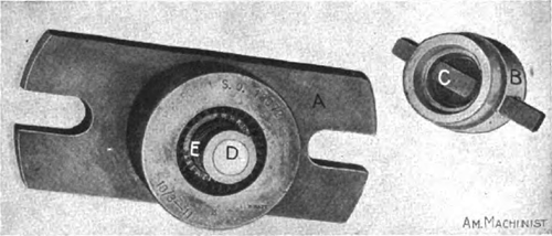
A set of dies used for making a pony snapswitch is shown, Fig. 7. The dies are fastened and operated in a manner similar to those already described, A being the female and B the male die. One of the finished parts is shown at C. Fig. 8 shows the dies used for making a corrugated top for a sign receptacle. The female die is shown at A and the male die at B.
The method used for ejecting the finished piece is rather novel and different from that described for the previous dies. When the male die fits into the lower die for the molding operation, the bar C sets down on the plug D compressing a spring which sets against the under side of the bar C. When the die B is released the spring pressure is also released and the bar forces out the finished molded part from the inside of the die. The forming core E is then acted upon by a spring moved by a lever by the operator, thus forcing out the molded part from the female die.
DIES FOR MOLDING FUSE BASES
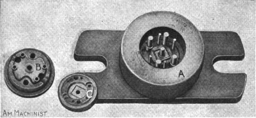
The dies used for molding three-wire fuse bases is shown in Fig. 9. The female die A is fastened to the machine table and the male die B is attached to the plunger. The piece after being molded is ejected from the female die by the plate C, which is raised by rods controlled by the machine operator. The eight pins attached to the die fulfill the functions of cores and guide pins for the ejector plate.
| |||
| Fig. 9. Dies for Molding Three-Wire Fuse Bases |
 |
| Fig. 10. Dies for A Three-Way Branch Cutout |
 |
| Fig. 11. Samples of Porcelain Parts |
| |||
| Fig. 12. Maching One of the Dies |
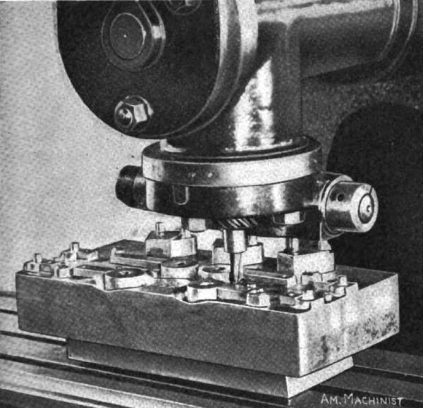
Fig. 10 shows the dies used for making a three-wire branch cutout. This is a more complicated piece than that shown in Fig. 9, but the operations of molding, and ejecting from the die, are the similar. Specimens of parts made in the dies Figs. 9 and 10 are shown in Fig. 11. The piece A is made in the dies shown in Fig. 9, and B in the dies shown in Fig. 10. These given an idea of the nature of the porcelain parts made by dies.
A Cincinnati universal miller, fitted with a vertical attachment, is shown in Fig. 12 profile milling one of the dies. These are carefully machined to templates and gages and afterward hardened and tempered to withstand any wear during use in the molding operation.
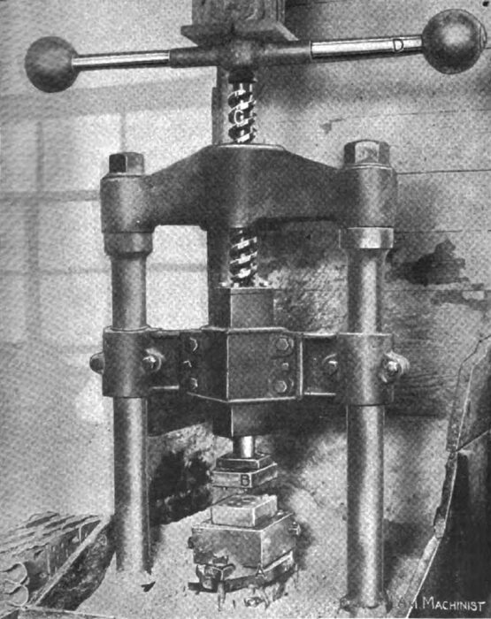
THE MOLDING MACHINE
One of the molding machines for making porcelain parts is shown Fig. 13. The female die A is fastened to the table as shown and the male die B is carried on the end of the screw plunger. After the clay, which is of the proper consistency, is filled into the lower or female die by the operator, the screw C is caused to revolve by means of the lever D, the balls at the end producing the required momentum. This carries down the guide plunger to which the male die is fastened. The dies coming together produce the molded part. The male die is then returned and the molded part is ejected by means of a lever controlled by the machine operator.
| |||
| Fig. 13. the Molding Machine |
| |||
| Fig. 14. A Closer View of the Machine |
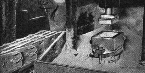
Fig. 14 is a closer view of the machine with the clay filled into the lower die ready for the impression to be made by the descent of the upper or male die. A number of the molded parts are shown on the left of the machine. After the parts have stood for a period enough to slightly hardenthey are carried to the trimming department, where all the fins are removed, afterward being dipped in a glazing solution. They are then put into firebrick crucibles and placed in a kiln, where they are baked or hardened at a temperature of 1200 deg. F.
All parts are made 9/64 in. to the inch oversize, this being the amount which they shrink during the hardening or baking process.
