[Trade Journal]
Publication: The Engineering Record
New York, NY, United States
vol. 43, no. 25, p. 590-593, col. 1-3
A 4,427-foot Span in an Electric Transmission Line.
Carrying high-tension electrical energy across navigable tide-water in cables which had to be held at least 200 feet above the high-water level is one of the features of the 140-mile transmission line of the Bay Counties Power Company of San Francisco. The waterway at the point of crossing is about 2,750 feet wide, and the topography of the land is such that a main span of 4,427 feet was necessary, involving the erection of three steel towers and a total cable system comprising four cables each nearly 6,400 feet long. Strong insulated saddles or cradles on the towers had to be designed, and the ends of each cable had to be insulated from the anchors, requiring insulating material of high compressive strength.
The Bay Counties Power Company is the result of a consolidation of two companies owning power plants in the Sierra Nevada Mountains, and has three power plants located on the North and South Branches of the Yuba River, the principal plant being at Colgate, Nevada County. For two years past it has sold power to the various cities along its lines to as far as Sacramento, and during the past six months has extended its service toward the Bay counties, terminating finally at Oakland, some 140 miles from Colgate. The extension to Oakland made it necessary to cross the Carquinez Straits, which is a narrow waterway separating Solano and Contra Costa counties and connecting San Pablo and Suisun bays. Through this water gate flow the waters of the Sacramento and San Joaquin rivers, as well as the ocean tides, making at all times a heavy and dangerous current. Because of the company's desire to avoid the expense of maintaining transformers at this point, which would be necessary to reduce the tension of the current with submarine cables, and its wish to transmit direct its high-voltage current, it was decided to cross with suspended cables, and the Pacific Construction Company of San Francisco undertook the work.
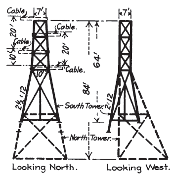
The survey showed the waterway to be some 2,750 feet in width, as stated, and 120 feet deep; a bluff, Dillons Point, on the Solano side (north side) to be 160 feet in height above high-tide mark; a hill on the south side, rising about 100 feet from the water's edge, some 60 feet high; and a general incline from there to about a 400-foot elevation, at half a mile south. In front of this bluff is the main line of the Southern Pacific Railroad, numerous telegraph and telephone lines, a hotel, warehouse and other buildings. The United States Government, in giving permission to cross here, required that a clear head-room for vessels of at least 200 feet above high tide must be provided; and to meet all requirements It was finally decided to construct a steel tower some 225 feet in height on Dillon's Point and one 64 feet in height on the south side and 4,427 feet distant from the high tower. In order to limit the height of the main tower to 225 feet this south tower was so located on the hillside as to bring its top 80 feet higher than the top of the main tower; and another advantage gained by thus limiting the main tower height lay in the fact that the land north of the tower falls away to a marsh at near tide level. Because of this low land it became necessary to turn the cables down to anchorage some 1,700 feet distant; and to do this a third tower was introduced, which, on account of the great change in the direction of the cables, was made to lean toward the north, taking its load normal to its foundations.
The general scheme is shown in an accompanying profile of the crossing. The three-phase, 40,000-volt, 60-cycle current of the Bay Counties Power Company is carried overland en two pole lines, 25 feet apart, one transmission circuit of three conductors to each pole line, the one a reserve to the other, in the event of breakdown. For the water crossing, conductors of a strength to stand the stress of the long span had to be substituted, and four 7/8-inch plow-steel cables were adopted, leaving one as a reserve. The insulation on main line, saddle and anchor insulators is designed to stand 60,000 voles, which pressure the company expects eventually to adopt, as the load increases. Each cable is counted equivalent in conductivity to a No. 2 copper wire.
The cables are stretched across the towers from anchor to anchor, from all of which they are insulated, and the land conductors are direct-connected with them near each end. The cables consist of 19 single-strand wires, weigh 1.6 pounds per lineal foot, and have a total breaking strength of 96,000 pounds, the unit breaking stress of the material being about 200,000 pounds per square inch. The wires had three coats of oil. Supporting nothing but themselves, each cable takes the form of a catenary which has a half span of 1,972 feet and a deflection of 147 feet, measured from the main tower, and a half span of 2,455 feet and a deflection of 227 feet measured from the south tower. On this basis each cable would have a tensile load at the main tower of 21,840 pounds, and at the south tower of 22,000 pounds. Experiments were made of the effect of the wind pressure, and the conclusion was reached that it might, in extreme cases, double the calculated strains, and the cables were considered amply safe for this. It has been found since that wind pressure will not strain the cables as much as assumed, as practically no shocks due to undulation will occur, simply a static pressure due to a certain lateral deflection of cables under heavy winds. It has been found that even in a gale the cables remain practically stationary at a certain lateral deflection, due to the wind, and do not produce undulations as had been expected; and further, it was surprising to find that instead of the cables being perfectly quiet in a calm, the undulations are quite noticeable both to the touch and to the eye. It was also found, unexpectedly, that before connection was made with the current the wind passing over the cables produced enough electrification to give quite a shock to the touch.
| |||
| The South Tower (Left). the Leaning Tower (Right). |
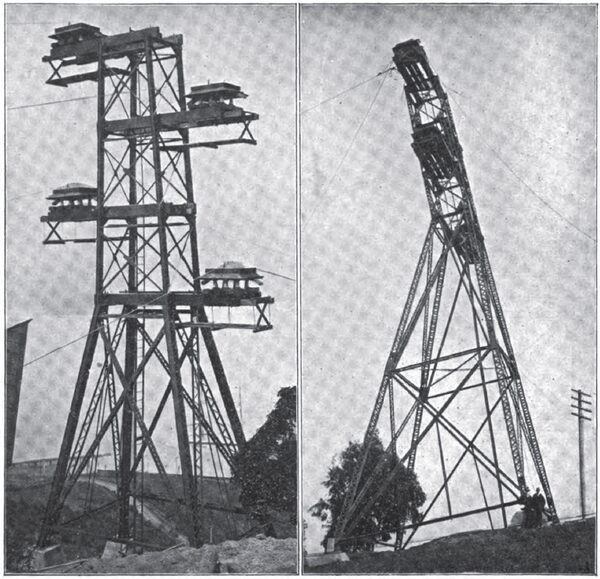
The four cables are carried on wooden arms, as shown in detail drawings herewith, two cables on each side, 20 feet apart vertically and horizontally. Each cable passes over the arm on five small wheels mounted on a cast-iron saddle and giving the cables a gradual bend in the arc of a circle of 8 feet radius. The saddle is lag-screwed to a double wooden timber flooring boiled in parafflne and covered with painted canvas and provided with gutters and run-offs for discharging rainfall at a safe distance on either side; the wooden structure is carried on special insulators, which in turn are fastened to the two main 7 ¾ x 15 ¾-inch supporting timber arms extending from the tower. Six insulators in all carrying the cradle structure, and these consist of four separate glazed porcelain shells cemented together with sulfur, and carried on a heavy steel cone which is enclosed in a conical porcelain sleeve. Each measures 17 inches in diameter and weighs about 75 pounds. The double timber cradle floor bears directly on top of the insulators and is held from displacement by timbers 5 ¾ inches thick, bored to fit the insulators, and fastened to the under side of the flooring. Underneath the heavy timber bracket arms for each cable is a light flooring supported from independent timber arms for the use of linemen in making repairs and inspections. The walk runs from a central iron ladder in the tower.
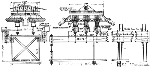 |
| The Insulated Saddle of Each Tower Arm. |
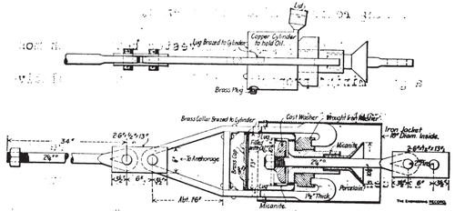 |
| One of the Pair of Insulators at Each Anchorage. |
 |
| Details of the Anchorage for Each Cable |
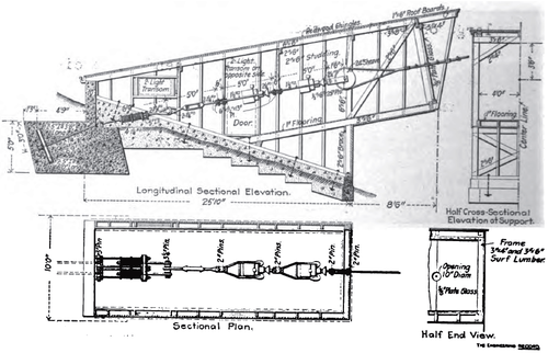
The arrangement at each end of each cable is shown in an accompanying drawing. The anchorages are masses of concrete in which are imbedded crossed I-beams, and from which extend steel eye-bolts, with pin connections, first to two sets of steel car springs, then a turnbuckle, then two tandem yokes connecting with heavy micanite insulators in copper cases that contain insulating oil, and last a 24-inch sheave around which the cable is turned and secured to itself for a distance of 15 feet with clamps and clips. Each insulator consists of a central iron rod holding a cast-iron washer on the end and of a heavy iron collar, between which and the washer is placed- the insulating material, and of an iron stirrup or yoke fitting into diametrically opposite points on the collar and passing to the other insulator or the turnbuckle, as the case may be. Each insulator takes the entire stress of the cable, two being inserted to halve the chances of a failure of the insulation with the high voltage employed. The bearing surface for the insulation for the average load on each cable, which is about 40,000 pounds maximum, is an annular ring of about 10.5 inches outside diameter and an area of about 57 square inches, which means 700 pounds per square inch. Micanite, as stated, was finally adopted as capable of withstanding the compression, and is 2 inches thick between the bearing surfaces. The central rod at the point of entrance into the insulator is provided with a sleeve of porcelain, expanded into a funnel, which acts as a shield between the live rod and the insulated stirrup, and also interrupts surface leakage. The grooves on the outside of the micanite, as shown in a drawing of it herewith, were provided to increase the length of the creepage surfaces. The average block of concrete presents about 51.5 square feet cross-section transversely to the pull and contains about 16.5 cubic yards of concrete altogether. The anchorage apparatus is all encased in separate houses, built for protection against rain; they are well lighted, including a large plate-glass front, through a 9-inch hole in the center of which the cable passes, the non-conducting quality of the glass allowing this arrangement.
The towers are of iron and steel throughout, except cross arms for carrying the cable saddles. The main tower is 225 ½ feet in extreme height from the foot of the lowest columns, and has a base about 68 x 90 feet. The four main posts are each made of two 12-inch channels, battered in both directions, to center distances of 9 ½ x 6 ½ feet at a point 30 ½ feet below the top, above which they batter in one direction only to a top width of 6 ½ feet both ways. The channels in the columns vary in size from 12-inch 30 pounds at the base (reinforced by one 5 x 3-inch angle in each lower section), where they sustain a maximum compression of 132,510 pounds in each column, to 5-inch 6 ¼ pounds at the top, where they have 5,300 pounds compression in each column. The design was made to fit material on hand, as time was limited.
 |
| Tower Diagrams. |
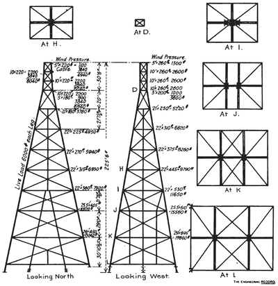 |
| Stress Diagram of Main Tower |
The pyramidal part of the tower is divided into stories from 20 feet high at the top to about 38 feet high at the bottom, braced with horizontal and diagonal struts in each face, as shown in the diagram. These struts are all made of four angles from 3 x 2 inches to 2 x 2 inches, pairs of them being latticed together with their flanges about 8 inches apart and their webs turned out from the center of the strut. Where these struts intersect, one of them is continuous and has a connection plate on each flange and the other one is cut to clear and riveted to each plate. These struts are connected to the columns by pairs of plates shop-riveted to the flanges and webs of the latter.
On the opposite transverse faces of the tower and in a parallel vertical plane midway between them, there is a pair of intermediate battered columns each composed of four 2 x 3-inch and 2 x 2-inch angles reaching to the fourth story, above which there is a single center column of four 2 x 2-inch angles reaching four stories higher. In each longitudinal face of the tower there is a similar center column seven stories high, and in all of them the two pairs of angles are latticed together with their flanges 8 inches apart, back to back, so as to pass through the horizontal and diagonal struts and be riveted to their flanges at intersections. The other vertical and inclined members in the lower stories of the tower are simply pairs of small suspension angles to support the centers of the long horizontal members. The main columns are spliced with flange and web plates just above the horizontal struts; all members were shipped separately and field riveted at intersections and connections. The main columns are anchored to crossed 4-inch I-beams in the bottom of the concrete blocks; the other columns are anchored with long bolts and washers built in the concrete. At every story the tower has 7/8-inch to 1 1/8-inch horizontal lateral diagonal rods which are pin connected to angles riveted to the columns and to extensions of the tie plates on the horizontal struts. The members and connections of the bent tower are similar to those of the main tower, except that in the transverse face the struts are riveted to the column-web splice plates, and elsewhere are riveted directly to the column channel webs without connection plates and that the lateral diagonals are single riveted angles. The columns are made of pairs of 8-inch channels, latticed, and the other members are each made of four 2 x 2-inch angles.
The method of erecting the cables was as follows: The cables (each about 6,400 feet in length) on reels, were horsed on a temporary wharf on the south shore. Heavy bents were built to carry the cables clear of the various wire lines, railroad and other obstructions, and the ends were then hauled up to the south anchorage by windlass, and secured to the anchorage system. The reels, one at a time, were then set on frames on a self-propelling steam barge, wooden brakes being arranged so that the revolutions of the reels could be easily controlled during transit; and with this barge augmented by a 50-horse-power gasoline launch, they were towed across the straits. On arrival at the north shore, the reel with the rest of the cable then remaining thereon was rolled ashore, horsed once more, and the cable run off and coiled on the temporary wharf provided for receiving it. The engine for pulling up the cables was located near the leaning tower and some 1,800 feet distant from the landing, and it was set to face the north anchorage. From the engine, and leading through a block at the anchorage and over both the leaning and main towers, a hemp line was run to haul over the slack end of the cable. This hemp line pull brought the end near to the leaning tower and a steel line was attached and the cable end pulled over the leaning tower far enough to reach the end of the main pulling pennant used for the final pulls. The four cables were raised in five days. The Pacific Construction Company had to provide its own patrol boats and keep out of the way of the water traffic.
The plan of the crossing, including designs of towers and anchorage connections, as well as the plan for hoisting the cables, was worked out by Mr. P. A. Koetitz, chief engineer of the Pacific Construction Company, and were approved by Mr. R. H. Sterling, division engineer of the Bay Counties Power Company, and Mr. J. D. Galloway, consulting engineer of that company. The erection was done under the general direction of Mr. Koetitz, and the immediate supervision of Mr. F. M. Butler, secretary of the Construction Company, and Mr. F. B. Field, its general superintendent. The insulators at anchorages and on the towers are the design of Mr. Sterling. The principal officers of the Bay Counties Power Company are Mr. E. J. de Sabla, Jr., president and general manager; Mr. F. M. Ray, assistant manager; Mr. C. A. Grow, secretary and treasurer; Mr. L. M. Hancock, general superintendent. The president of the Pacific Construction Company is Mr. C. F. McCarthy.
