[Trade Journal]
Publication: Electrical World
New York, NY, United States
vol. 58, no. 21, p. 1237-1243, col. 1-2
THE WORLDS PIONEER HIGH-TENSION TRANSMISSION SYSTEM.
THE GENERATING AND TRANSMISSION SYSTEM OF THE TELLURIDE POWER COMPANY.
Evolution from 100-hp Generator in 1890 to Eight Generating Stations Aggregating 40,000 hp and Supplying 600 Miles of Transmission Line in Three States.
|
OF the modern systems of high-tension electric transmission which are revolutionizing industrial conditions within economic radius of their generating stations, that of the Telluride Power Company occupies a place of unique interest. The organization enjoys the distinction of being the pioneer enterprise of its character in the world, the company having been the first to undertake commercially to transmit high-pressure energy, antedating the celebrated Frankfort-Lauffen experiment of 1891 by about a year. In the light of modern transmission practice, with its increasing reliability of service over distribution areas covering in many cases thousands of square miles of diversified country, the work of the initial plant at Ames, Col., seems to belong to the remote past, and yet it is barely a score of years since the triumph of electricity in that remote mountainous district at the hands of Messrs. L. I. and P. N. Nunn disproved the skepticism of the outside world and signalized the beginnings of the present great dual systems of the company in Colorado, Utah and Idaho, comprising eight power stations having a rating of over 40,000 hp, 35 miles of flume and pipe line, about 600 miles of transmission lines, 400 miles of telephone line and distributing networks. An outline of the operating conditions of the system in Colorado and Idaho was given in our issue dated July 15, 1909.
It is noteworthy that the original work at Ames was based upon the necessity of supplying energy at a figure competitive with steam, the situation being acute on account of the prohibitive cost of coal in the San Juan district. In these days of operating economy it is easy to lose sight of the fact that the pioneers of hydroelectric transmission were obliged to develop their markets through the most vigorous competition with the established forms of motive power and to operate their systems with apparatus which was crude and experimental to the last degree. That it was possible to attain commercial success in the face of such obstacles speaks volumes for the courage and ability of the financiers and engineers associated with the early history of the art and encourages the belief that subsequent progress is but the preliminary to a future development beside which the work of to-day will appear incomplete and probably as crude relatively as the original practice seems to the modern observer.
The history of the Telluride Power Company is a continuous record of independent research in the transmission field, and the organization has never sacrificed the lead which its management assumed in establishing the Colorado service of 1890. From the first experiments with 3000-volt synchronous transmission at Ames to the latest investigation of automatic relays suitable for operation in networks the company has maintained the spirit of scientific investigation within its organization, co-operating with the manufacturing companies, no less than determining its own advanced standards of equipment and methods. At its headquarters at Olmsted, Utah, the company to-day maintains a research laboratory which would do credit to any university, and the facilities there afforded for experimental study of transmission problems are unique in commercial power organizations.
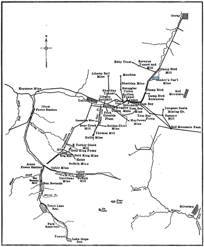 |
| Fig. 1 Map of Colorado System. |
EARLY DEVELOPMENT.
Only passing mention can be made of the company's early development in connection with a survey of the present systems. The initial plant was installed at Ames in order to meet a critical industrial situation at the Gold King mill, situated at an altitude of 12,000 ft. and in the heart of one of the richest and most rugged gold-bearing districts of the Rocky Mountains. On account of the excessive cost of steam servicesoft coal selling at about $35 per ton at the millthe property was confronted by an attachment, whereas its commercial success would have been assured with a substantial profit had it been possible to produce energy at $100 per hp-year. A stay of proceedings was secured and a generator and motor, wound for 3000 volts, single-phase, and rated at 100 hp each, were installed and connected by two No. 3 bare copper wires mounted upon short Western Union cross-arms and porcelain insulators, the line being 2.6 miles in length. The generator was installed in a rough cabin on the site of the present Ames station and belt-driven from a 6-ft. Pelton waterwheel operating under a head of 320 ft. The generator and motor were duplicate Westinghouse alternators, the largest machines manufactured at that time. The generator was separately excited, the motor being self-exciting. Each was provided with a twelve-part commutator and was slightly compounded through series transformers mounted upon opposite spokes of their armatures, the latter being of the iron-clad type, with twelve coils carried in fuller-board and mica cells. Circuits were closed with jaw switches and opened by arc-lamp plugs. Less than 5 per cent loss was encountered in the line and the cost of copper was only $700, compared with an estimated expense of $70,000 for copper with direct-current energy transmission. The motor was brought up to synchronous speed by a single-phase induction starting motor, the latter being turned initially by hand on account of its feeble starting torque. The initial plant ran thirty days without a stop. Many difficulties were encountered and overcome, notably those arising from the severe lightning storms of the district, which comprises some of the most exposed mountain ranges in the United States. The use of T-toothed armatures with replaceable coils proved to be the plant's salvation, but the excessive number of burnouts led to the construction of various types of lightning arresters, leading to the development of the Wurts non-arcing equipment.
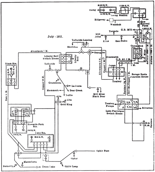 |
| Fig. 2 Diagram of Colorado System. |
EXPANSION OF ORIGINAL SYSTEM.
The success of the Ames plant soon resulted in the expansion of the system, a 600-hp generator being installed in 1892, with transmission to a 250-hp motor to miles distant. In 1894 the transmission distance was increased to 54 miles, energy being supplied to motors in the famous Savage Basin, near Telluride. In 1891 the company's first lighting transformer was placed in service, and experience soon demonstrated the value of immersing the device in engine oil as a protection against lightning. Alternators were first paralleled by the company in 1893.
Even in these early days the value of technical education was appreciated by the company and special facilities were accorded station operators for the prosecution of daily study and shopwork, with a technical library and laboratory constantly at hand. In 1896 the Tesla induction motor system superseded the synchronous installations. In 1900 the company built a 1200-kw generating plant at Ilium, 6 miles below Ames on the south fork of the San Miguel River, the machine being directly connected to two impulse wheels operating under a 500-ft. head. Duplicate transmission lines were installed and among the contemporary improvements effected were the use of masonry compartments for transformers, the provision of line sectionalizing switches of the open-air type, the installation of junction houses at distributing centers, use of recording instruments, inauguration of a 10,000-volt underground transmission at the Gold King mine, and in 1895 the institution of the celebrated experiments with transmission at potentials of from 30,000 volts to about 60,000 volts.
The latter experiments were undertaken to throw light upon the feasibility of transmitting electricity over larger areas from important water-power plants contemplated in Utah and Montana by the company.
The original plant at Provo, now known as the Nunn station, contained two 750-kw, 800-volt, 60-cycle, three-phase generators directly driven by horizontal twin turbines operating under a head of 125 ft. From this plant energy was transmitted over a single line to Mercur, 32 miles distant, at a pressure of 40,000 volts, this being the first commercial system operating at the above potential, which was at the time nearly three times the voltage previously employed by any transmission company in its service. The Provo-type insulator, a triple-petticoated glass outfit, with double neck and serrated bottom edge, was developed for this service, and on some of the older portions of the present system these insulators are still in use, although porcelain was long since adopted as the company's standard. In 1901 a plant was installed at Logan, Utah, containing two 1000-kw revolving-field alternators directly driven by waterwheels operating under 212 ft. head, this plant being tied to the Provo system by duplicate lines over 100 miles long. A new station at Olmsted, near Provo, was completed in 1905, this containing three 2400-kw generators directly driven by waterwheels operating under 340 ft. head.
LATER DEVELOPMENTS.
The later growth of the system includes the addition of a 300-kw station at Ouray, Col., in 1905; the construction of a 3600-kw station near the site of the original plant at Ames; the rebuilding of the Ilium station, and the doubling and extension of the transmission system in the Telluride district, with the construction of new lines into the Red Mountain region and many additional branches to new consumers. Within the Utah department of the company, which operates a system having no electrical connection with that in Colorado, a plant at Jordan Narrows was purchased in 1906, its rating being 1300 hp; a plant at Battle Creek, a few miles from Olmsted, was built in 1906, with 2400-kw equipment; and in 1906-7 a new plant was built by the company at Grace, Idaho, the total rating of the generating units being 11,000 kw. This station is connected with the Logan plant by duplicate transmission lines and was designed for ultimate operation at 88,000 volts.
The Colorado department of the company serves a market situated in the rich mining districts of San Miguel and Ouray Counties, and within easy transmission distance of the San Juan district are fertile agricultural lands and promising towns. Apart from the mining load, which is extremely stable in this locality, the requirements of lighting, industrial motor service and irrigation are such as to indicate substantial increases in output in the future.
The Utah department serves a diversified market located in general within from 50 miles to 75 miles of Salt Lake City, including the supply of energy to the local central-station organizations at Salt Lake and Provo and to the noted mining camps of Bingham, Garfield, Eureka. Mercur, Topliff and to various important industrial organizations. All the electric railway systems in Utah now receive their energy wholly or in part from the Telluride Power Company. Important irrigation and pumping projects are also under consideration.
WATER RESOURCES. COLORADO DEPARTMENT.
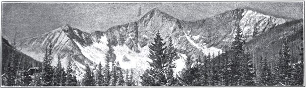
The sphere of operations of the Colorado department lies within the so-called San Juan district, in the southwestern part of the State. About 6 miles southeast of Telluride an apex in the mountain range forms the divide of three watersheds draining into the following rivers: The Uncompahgre, flowing north into the Gunnison; the south and east forks of the San Miguel, uniting west of Telluride and flowing into the Dolores and later the Grand River; and the Animas River, flowing south into the San Juan. The Dolores also rises near the apex and flows southwest into the Grand River. Topographically the region is characterized by mountain peaks attaining elevations of from 13,000 ft. to 14,000 ft. above sea level, the mean elevation of the intervening valleys and basins being from 5000 ft. to 9000 ft. Heavy forest growths abound upon the western and northern slopes of the divide. In spite of the fact that the lowlands surrounding the headwaters are arid the precipitation upon the region near the divide is heavy, ranging from 40 in. to several times that amount at higher elevations. Perpetual snow is found on the higher portions of the range and the run-off is great on account of the rocky character of the basins.
The total drop from the highest lake on the headwaters of the south fork of the San Miguel River to its mouth, a distance of 12 miles, is about 4000 ft. The south fork is formed by two branches known as Lake and Howard's forks, which head near the summit of the divide. All the waters of the south fork are controlled by the power company. A system of three reservoirs holds a portion of the flood waters of Lake Fork for use during the period of minimum natural flow. Lake Hope, the highest reservoir, 11,700 ft. above the sea, has an area of 38 acres at spill level, with a very great depth, due to a crater formation. The surface of the original lake has been raised by a rock-filled dam, 20 ft. high, with rubble masonry on the water side, a water-tight face being formed by horizontal sheeting spiked to timber embedded in the masonry. An outlet tunnel taps the lake 140 ft. below spill level, and the outflow is controlled by an 18-in. valve and pipe carried through a masonry bulkhead. The reservoir capacity is 140,000,000 cu. ft. Water from the lake flows through a natural channel 3 miles long into Trout Lake, a natural reservoir of 162,000,000 cu. ft. storage capacity, located at an altitude of 9700 ft. and having a surface area of 142 acres. Between Lakes Hope and Trout is situated a middle reservoir with a storage capacity of 30,000,000 cu. ft. The drainage area above the outlet of Trout Lake is 14 sq. miles, the total precipitation on which, less evaporation, is available for hydroelectric development. The high-water period lasts from about June 1 to Oct. 1. During the seven winter months stored water is necessary to supplement the natural stream flow.
Howard's Fork heads about 4 miles above Ophir and after flowing 8 miles it joins Lake Fork at Ames. Although no storage has been developed on this stream, full advantage may be taken of the varying stream flow during the dry months by using the Lake Fork reservoirs to supply only the difference between the Howard's Fork flow and the power demand.
The Uncompahgre River rises on the northern slope of the divide, several miles east of Telluride and about 8 miles south of Ouray, thence flowing northward through Ouray to the junction with the Gunnison River. The watershed is similar topographically to that of the San Miguel River, the slopes being rugged with steep sides and heavy forest growths. At Ouray the drainage area is about 24 sq. miles. The high-water season begins from one to two months, earlier than in the Lake Fork watershed, making the watershed of inure value than the minimum flow indicates. Between the points of diversion and return to the plant at Ouray the stream drops 470 ft. in a distance of 6200 ft.
| |||
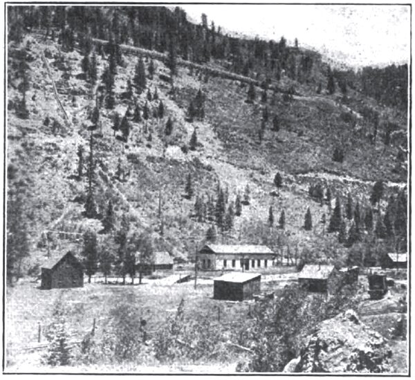
| Fig. 3 View of Ames Station. |
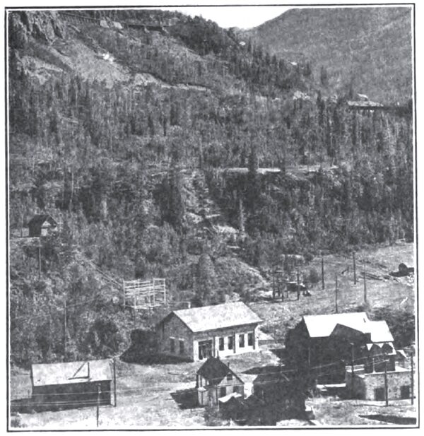
NEW AMES PLANT.
The Ames power station is located near Ophir, at the junction of Lake and Howard Forks of the San Miguel River. From Trout Lake an outlet pipe 42 in. in diameter taps the lake 30 ft. below the spillway, there being an intake well of concrete, 9.5 ft. x 12 ft. x 9 ft. inside dimensions. The flow is regulated by a 42-in. Chapman sluice gate. The outlet pipe discharges into a 24-in. x 30-in. wooden flume 13,000 ft. long and having a grade of 4.8 in moo. The flume ends in a steel tank which provides peak load storage and assists regulation. From the regulating tank a steel penstock 270o ft. long carries the water to the power house, the upper end being steel-riveted and the lower end lap-welded pipe, the diameter varying from 30 in. to 26 in. At the bottom of the penstock there is installed a "Y" with a gate valve in each branch, the arrangement permitting the use of the water in either the new or the old station at Ames. The water from Howard's Fork is carried about a mile along the mountain side from the point of diversion in a 24-in. x 3o-in. wooden flume. terminating in a pressure box from which a penstock of riveted and lap-welded steel pipe 2000 ft. long and from 24 in. to 18 in. in diameter leads to the plant, terminating in a valved "Y" also allowing the use of the water in either the old or new sections of the station.
| |||
| Fig. 4 Generating Unit at Ames Station. |
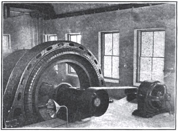
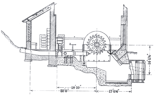
The Ames plant consists of two sections, one containing a 3600-kw generating unit with two waterwheels mounted upon a common horizontal driving shaft, and the other housing two 600-kw generators, each being directly connected to a waterwheel. The larger unit is installed in a new stone building known as the Lake station, and by the "Y" connections in the pipe lines above mentioned the generator may be driven either by a 5000-hp wheel drawing water under a head of 918 ft. from the Lake Fork system or in part by a 1200-hp wheel taking water from the Howard's Fork supply. This wheel is not shown in the station drawing, but the wheel-pit and generator-shaft extension for it are indicated. The station building is 58 ft. x 48 ft. over all, with standstone foundations laid in cement on concrete footings, the roof being of shingles carried on steel trusses with metal lath and plaster on the under side. The larger wheel is a Pelton outfit, with deflecting needle nozzle operated by a hydraulic cylinder under penstock pressure, the control being by pilot valve near the switchboard. The flow to the nozzle is controlled by a 24-in. hydraulically operated gate valve. The 1200-hp wheel is also a Pelton equipment, delivering its rating under a gross head of 626 ft. The nozzle is of the rigid needle type with stream deflector operated either by governor or by hand, the needle being controlled by hand wheel and gearing. The 3600-kw generator is a three-phase, 11,000-volt revolving-field machine of General Electric make, with a 75-kw, 125-volt exciter belt-driven from the shaft at a speed of 550 r.p.m.
ELECTRICAL. FEATURES.
Energy front the generator is passed through an oil switch in the basement near the foundation and carried in 11,000-volt, rubber-insulated cables in fiber conduit along the basement ceiling to a bus structure mounted in concrete framing with asbestos barriers beneath the station switchboard, which is a four-panel installation located on the floor of the operating room, the latter being of reinforced concrete. On the main floor of the station five line switches of 15,000-volt rating are mounted in concrete cells and controlled from the switchboard by bell cranks. The switchboard contains one generator panel and three panels controlling two feeders each, with the usual instrumental equipment. On a reinforced-concrete gallery above the switchboard are mounted instrument transformers and protective apparatus consisting of spiral choke coils and electrolytic lightning arresters connected for the ungrounded neutral operation. Automatic overload relays are installed in connection with the oil switches on each of the outgoing lines, which leave the building through fiber concrete bushings set in sewer tile. In the operation of the station the Howard's Fork wheel of 1200-hp rating utilizes the total of the varying stream flow so far as possible, the plant drawing upon the Lake Fork system merely for the rest of the demand. Three 400-kw transformers are installed in a corrugated-iron building outside the station for supplying energy at 17,500 volts to a feeder serving Ophir Pass. Disconnecting switches are installed on each side of the feeder oil switches in the station.
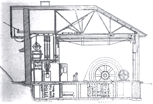 |
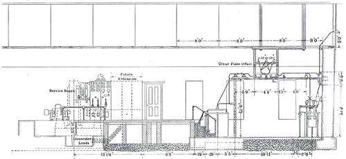
| Fig. 5 Cross-Section of Ames Station. |
 |
| Fig. 7 Cross-Section of Ames Station. |
| |||
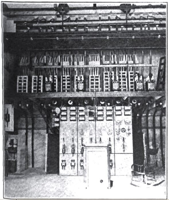
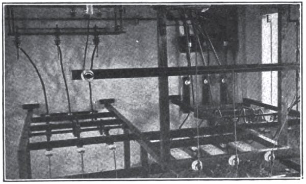
| Fig. 6 Ames Station Switchboard and High-Tension Gallery. |
OLDER AMES PLANT.
The older section of the Ames station illustrates the last remodeling of the company's earliest development in Colorado, utilizing the same waterways as the new section and serving mainly as a relay to the latter. The hydraulic equipment consists of two 900-hp Felton wheels, each flexibly coupled to a 600-kw, 500-volt, two-phase Westinghouse generator operated at 327 r.p.m., the generators being of the revolving armature type. Each wheel is equipped with gate valves and deflecting nozzles, and one uses Howard's Fork water under a gross head of 626 ft., and the other Lake Fork supply under a gross head of 918 ft. Two 22.5-kw exciters are provided, each being belt-driven from the generator couplings. The generator leads are carried under the floor to a seven-panel switchboard, from which connection is made to four 375-kw transformers which raise the potential to 11,000 volts, three-phase, for the transmission of energy throughout the system. The outgoing leads are rubber-insulated cables carried on glass insulators, connecting with fused air switches and line outlets. Spiral choke coils and Westinghouse type "C" lightning arresters are installed in the old station. The two sections of the plant are tied together on the high-tension side, the jumper line being carried out of the old building through paraffined oak bushings.
| |||
| Fig. 8 View of Ilium Station. |
ILIUM PLANT.
The Ilium station is located about 5 miles below Ames on the Lake Fork of the San Miguel River. Water is supplied directly from the Lake and Howard Forks and also from the tailrace of the Ames plant, in addition to which several small creeks are diverted into the flume connecting the two stations. The waterway consists of 28,600 ft. of wooden flume, 42 in. x 32 in. in section, and 873.5 ft of pipe line. The lower end of the flume, 750 ft. long, is enlarged to a 12-ft. x 16-ft. section to provide peak-load storage. The penstock is of lap-welded steel pipe with flanged joints, the diameter varying front 32 in. to 28 in., The station building is an uncoursed rubble structure, 74 ft. x 30 ft. outside dimensions, with a 12-ft. x 22-ft. shop under the same roof. Stone foundations are used; all floors are of reinforced concrete, and the roof is carried on a steel-truss installation. A 15-ton crane serves the operating room.
The generating equipment consists of a 1200-kw, 1050-volt, three-phase General Electric revolving-field alternator, running at 200 r.p.m. and directly driven on a horizontal shaft by two 8-ft. Pelton waterwheels. The lower end of the penstock terminates in a "Y-casting," to each branch of which is attached a 12-in. gate valve with a deflecting nozzle operated by a hand lever. The wheels deliver a total of 1600 hp under a head of 48o ft. net. On the inboard supply pipe a motor-operated needle is installed, the motor being a 2 hp, 220-volt induction equipment geared -through a worm to the driving mechanism. A 25-kw, 125-volt exciter running at two r.p.m. is belted to the coupling between the generator and the wheels. From the generator insulated leads are carried along the basement wall to an oil switch beneath the switchboard, which consists of two panels, one controlling the generator and the other two outgoing feeders. Overload relays are provided for disconnecting defective lines. At the end of the operating room three 400-kw, 1050-volt to 11,000-volt Converse transformers are installed in a bay below the operating-room floor level, the connections being delta on both the primaries and the secondaries. Beyond the transformers the outgoing leads are passed through two 15,000-volt oil switches to the lines, the connections being so made that lines may be looped through the station operating the generator, or if desired the latter may be operated on either or both of the incoming lines. Hourglass choke coils and electrolytic lightning arresters are installed, and the outgoing lines emerge from the building through Locke 15,000-volt outlet bushings. The usual disconnecting switches are provided on each side of the feeder switches. A 10-kw lighting transformer for station service at 110 volts is in service. In order to indicate the height of water in the pressure box use is made of a float with a mechanical connection to a rheostat arm in series with a voltmeter on one side of a 110-volt circuit. The voltmeter is calibrated in depths of water and shows the conditions at the pressure box by readings determined by the position of the float arm.
 |
| Fig. 9 Section of Ilium Tower Station. |
| |||
| Fig. 10 High-Tension Framework at Ilium Station. |
OURAY PLANT.
The Ouray station of the company is a plant of 300-kw rating, located in the town of Ouray, on the Uncompahgre River. About a mile above the station a dam of the rubble-masonry arched type, 85 ft. high, 75 ft. long and about 16 ft. thick, is in service between cliffs on each side of the river. From the dam a total length of 6200 ft. of riveted steel pipe, varying in diameter from 30 in. to 22 in., connects with the power house, the intake being about 8 ft. below the top of the darn. A single head gate regulates the flow. Air valves and expansion joints are included in the pipe line, and the total head from the reservoir to the shaft center is 440 ft.
The generating equipment consists of a 200-kw, 2200-volt, two-phase alternator, direct-connected to a pair of Pelton wheels, and a 185-kw, 2300-volt single-phase machine belted to the same prime mover and used for local lighting. Two Scott connected 200-kw transformers serve to connect the station to the transmission system.
| |||
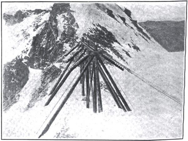
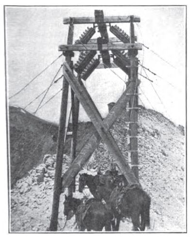
| Fig. 11 Strain Tower, Camp Bird Divide. |
| |||
| Fig. 12 10,000-Volt Transmission Tower at Camp Bird Divide. |
COLORADO TRANSMISSION SYSTEM.
About 90 miles of three-phase, 10,000-volt, 60-cycle lines comprise the transmission and distribution system of the company in Colorado. The principal center of load is at the Savage Basin, near Telluride, where a junction house has been erected near the Tomboy Mine, 12,000 ft. above sea level. Main lines extend from each power station on the system to this junction house, consumers being supplied with energy by feeders running from this junction house and by taps from the main transmission lines. A comprehensive system of loops, cross-overs and junctions forms an insurance of the service against line failures.
The system load-factor on a monthly basis is about 80 per cent and the power-factor about 78 per cent. The conditions are tending toward the gradual installation in the future of a 17,000-volt system, with shorter spans on the pole lines on account of the severe weather conditions encountered. Considerable difficulty has been experienced with the breakage of aluminum lines in the winter season and from swinging short-circuits in summer. In bad localities the transmission wires are frequently separated by a 4-ft. spacing, but in ordinary wooden-pole construction the spacing is somewhat less.
All power stations and important switching points are connected by a private telephone system, the operating headquarters of the company being at Telluride. The telephone lines are carried on separate poles at a safe distance from the main circuits.
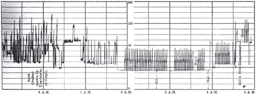 |
| Fig. 13 Load Fluctuations in A Mill and Mine Installation. |
GRAPHIC METERS.
The use of recording meters has attained a considerable development in both Colorado and Utah Departments. A typical curve from a mine and mill installation is shown herewith, the instrument showing the power fluctuations clearly as the various machines are thrown into and out of service. In the case in hand the mill demand was fairly constant at 35 kw; the operation of a 300-ft. hoist imposed an instantaneous peak of about 75 kw upon the system, with a demand of 55 kw when hoisting steadily, and the addition of a rock crusher and compressor imposed fluctuations calling for a total demand of from 120 kw to 150 kw. The graphic meter also shows the time required to operate the hoist through the different steps of its cycle, the effect of coasting down the shaft, period of emptying and the time consumed in hoisting, etc. These instruments are largely of the electric winding type and furnish invaluable records concerning the extent and periods of power demand upon the system.
Descriptions of the Utah system will follow in subsequent issues.
