[Trade Journal]
Publication: Electrical World and Engineer
New York, NY, United States
vol. 39, no. 20, p. 843-850, col. 1-2
The Cincinnati Gas and Electric Company
VISITORS to the National Electric Light Convention of 1902, at a Cincinnati, will find the electric light central station work of that city undergoing a great change. The present time marks transition period in the electric light station work in Cincinnati. For a number of years previous to 1901 there were in Cincinnati three electric light companies controlled by the Cincinnati Gas Light and Coke Company besides the Cincinnati Edison Electric Company. The three companies controlled by the Cincinnati Gas Light and Coke Company were the Jones Brothers Electric Company, the Brush Electric Light Company and the First Cincinnati Edison Illuminating Company. years. The war between these three allied companies controlled by the gas interests on the one hand, and the Cincinnati Edison Electric Light Company on the other, waged hot for several years. Indeed, it is doubtful if a more fierce competition in the electric light business has taken place in any large city in the United States in recent years.
| |||
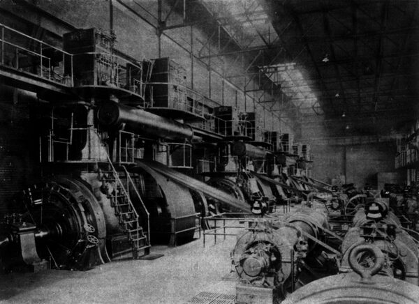
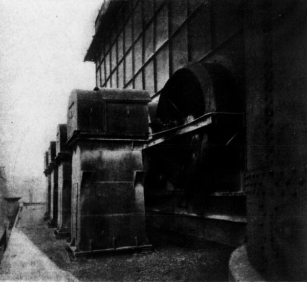
| Fig. 1.Engine and Generator Room, Now Being Altered. |
After several years of this war, in which rates were cut indiscriminately and a great tangle of pole lines run over the city, a consolidation was effected early in the year 1901, by which all the electric light central station companies and the gas company were merged into the Cincinnati Gas and Electric Company.
The officers of the Cincinnati Gas and Electric Company are: General A. Hickenlooper, president; Norman G. Kenan, first vice-president; C. W. Wetmore, second vice-president; Henry W. Sage, secretary; Charles J. Foust, treasurer.
The electrical department has as its general superintendent, H C. H. Hutchinson, with Charles Jones. superintendent of stations, and J. Pfiester, superintendent of electrical distribution. These gentlemen have before them no small task. In place of supplying energy from four different central stations, three of which are out of date, everything is to be changed over for supply from one central generating plant. This central generating plant will be the one formerly used by the Cincinnati Edison Electric Company, but very much enlarged in capacity and changed in various details to be described later. At the present time, in Cincinnati there is an immense net-work of wires overhead in the down-town district. The old Edison three-wire net-work was, of course, underground, but everything else was overhead.
A most important change now being made is the putting underground of all the wires within a certain district in the down-town portion of the city. The territory covered by the companys lines, both over- head and underground, can be seen from the accompanying outline map, Fig. 6. This territory is roughly 43 square miles. The greatest distance from the power house, from which current is supplied, is eight miles. The underground district recently established is irregular in shape, about 6,000 feet long by 3,200 feet wide. The main which power house, from which all current is to be supplied, and is now furnishing the largest part, is at Plum and Charles Streets.
During the present season underground conduit is to be laid in 43 miles of street. This conduit will be supplied by the American Vitrified Conduit Company, and laid, under contract, by Guy M. Gest. The underground lead-covered cable to go in this conduit is being made by the Safety Insulated Wire and Cable Company. At the present time all of the street lighting of the city is being done by continuous current, series, 9.6 ampere arcs, supplied by Brush arc machines. There are now 3,408 of these lamps on the city circuits, for which a price of $84.90 per year is obtained. These are to be replaced by 4,400 enclosed, alternating current, series arcs of 300 watts capacity, or 4 amperes at 75 volts. For these new lamps the contract price is $72.00 per year in the underground district, and $60.00 per year in the outside, overhead district. In the underground district the cable used for the series arc lighting will be No. 6 copper wire with rubber insulation 7-32-inch thick, lead covered.
In the underground district the neat forms of iron pole and brackets, shown in Figs. 4 and 5, will be put up. In the overhead districts iron brackets of the form shown in Fig. 2 are to be used for supporting the city arc lamps. The base, shown in Fig. 4, has a flange bolted to the sidewalk and a portion extending 30 inches below that. Both poles and brackets are the work of the Electric Railway Equipment Company, an order being under way for 1,000 poles and 3,600 brackets. The arc lamps are of a new type of the General Incandescent Arc Light Company, Fig. 3.
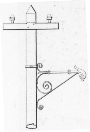 |
| Fig. 2.Arc Lamp Bracket for Wooden Poles. |
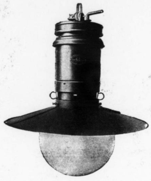 |
| Fig. 3.Arc Lamp to Be Used on All Street Lighting. |
As the central station is situated in close proximity to the down town district, the direct-current, three-wire, 110-220-volt net-work will be retained for supplying light and power for the underground district. This district will be supplied direct from the power house by direct-current generators, as heretofore. All the rest of the companys current will be generated as 60-cycle, alternating-current. three-phase, with 4,000 volts between each phase and 2,200 volts between each leg of the circuit and the neutral wire when connected Y-fashion. For the series arc lighting, this will be transformed by General Electric tub transformers located at the central station to supply 4-ampere, 60-light circuits. For light and power in the residents or outlying districts, the four-wire, three-phase system is used. Where motors are to be run from this alternating current circuit, the motors or their transformers are connected delta fashion to the three outside legs of the circuit without making use of the fourth or neutral wire. For residence lighting, transformers wound for a primary voltage of 2,200 are connected between the outside legs of the 4,000-volt circuit and the neutral wire.
The transformers will, of course, be distributed so as to maintain as nearly as possible the necessary balance between the three Secondaries of these transformers are wound for 110-220-volt three-wire circuits. At the present time, these secondary distributions in the residence districts are not run as connected together net-works, although they are arranged so that they can be so run if desired. Each transformer supplies its own section of secondary wiring, and there is no connection between the secondary circuits supplied by one transformer and those of another. The reason for this separation is that it has been found there is too much danger of overloading some of the transformers connected to the net-work, in case the fuses blow out on other transformers connected to the net-work.
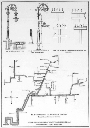 |
Cincinnati is divided by its almost mountainous hills into a number of fine residence districts, each of which is located on its own hilltop. The incandescent lighting of such districts is supplied by two of these four-wire, three-phase feeder circuits, shown diagrammatically in Fig. 6. These supply Clifton, Avondale, Mt. Auburn and Walnut Hills. The number of transpositions and the way in which transformers are balanced between the various circuits can be seen from Fig. 6. Considerable care was used to see that these circuits were all transposed at proper intervals. As will be seen, there are three transpositions between the power house and the point where feeders begin to be tapped, making a complete transposition of the three-phase, four-wire mains. The method of accomplishing the transposition is shown by Figs. 7, 8, 9 and 10. Fig. 7 is the ordinary arrangement of wires on the cross-arm before reaching a transposition. In Fig. 8, the first step in the transposition has been made by putting a second cross-arm below the main crossarm and dropping one of the four wires to the lower cross-arm. In Fig. 8 the wire 1 is the one which has been dropped. In Fig. 9 the second step in the transposition is made by running wire 1 diagonally across to a pin on the opposite end of the lower cross-arm from that occupied in Fig. 8. Here also, wires 2, 3 and 4 on the upper cross-arm have all been moved one pin to the right, leaving vacant the pin at the left end of the cross-arm. In Fig. 10, wire 4 has been placed on the upper cross-arm, and the pole line resumes its normal form. The insulators on the 4,000-volt, alternating-current lines, as well as on the new series arc circuits, are 4-1/4-inch diameter glass, made by the Hemingray Glass Company.
In the central generating station, as well as on the street, visitors will find a great change going on. Not only is the station being enlarged to take care of the entire business formerly supplied from a number of stations, but part of the machinery installed is being changed. This plant formerly consisted of a mixture of series arc and direct-current, direct-connected, 110-volt dynamos. To be more explicit, the equipment early in this year in the generating room consisted of five 1,600-hp, vertical, cross-compound, condensing. Reynolds Corliss engines, each driving, by means of a counter shafting, twelve 1oo-light Brush series arc machines; moreover, each engine also had direct-connected on its shaft two 110-volt direct current dynamos for supplying the Edison three-wire net-work. Each engine unit thus supplied both are and incandescent lighting. which was a very flexible arrangement in one way, *because there would be portions of the day when there would not be sufficient arc lighting to take the full capacity of one engine. In addition to the combination units just enumerated were two 2,500-hp engine of a similar type, direct connected to both direct-current and alternating-current generators. The plant, as it existed before the present charges were inaugurated, can be seen in Fig. 7. The counter shafting for driving the arc dynamos was driven from the engines by a rope drive and the arc dynamos belted from the counter shafting. The arc dynamos are now all being taken out and the direct current dynamos on these engines are also being removed to make way for larger direct-connected machines, equal to the full capacity of the engine unit.
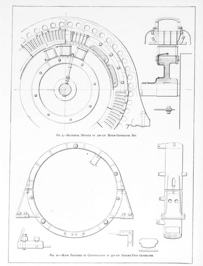
In place of these small direct-connected generators on the old engines there will be placed one 2,500-kw, three-phase Bullock alternator and four 450-kw, direct-current generators, for supplying the direct current Edison net-work. In addition to these direct-current. direct-connected units for supplying the Edison net-work at light load periods; and in order to make most economical use of the various generating units in the station, two 500-kw motor-generator sets have been ordered. These motor-generators will be arranged to take the 4,000-volt, three-phase alternating current at the motor end and generate 300-volt direct current for the outer wires of the Edison net-work. A 2,500-kw, direct-current machine will also be installed later.
The three-phase alternator, built by the Bullock Electric Manufacturing Company, is designed for 2,500 kw, normal load, and 3,120 kw, continuous overload. It will generate 4,500 volts between terminals, and operate at 75 r. p. m. The generator has 96 poles, and. therefore, produces alternating currents of 60 cycles.
The conditions for which this machine had to be designed are rather exceptional, as may be seen from the fact that the machine is the largest of its kind in this country. The generators in some of the New York traction companies stations have a larger output, but they are designed for 25 cycles and have not more than 40 poles while the generator built by the Bullock Company for the Cincinnati Company has 96 poles. It is apparent that the construction of a machine which requires the placing of so many poles on the circumference of a wheel offered problems to be solved by the engineers of a nature far more difficult than those that have to be solved for low-frequency generators, requiring only a moderate number of poles.
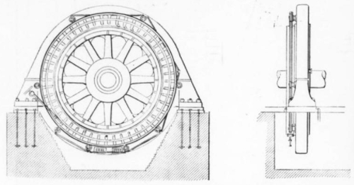
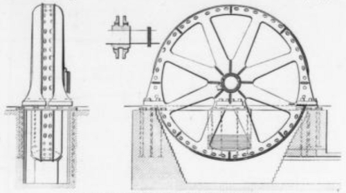 |
| Fig. 7.Elevations of Alternator. |
 |
| Fig. 8.Sectional Details of Alternator. |
 |
The general construction of the alternator may best be seen from Figs. 7 and 8, showing a detailed assembly and an outline of the generator, respectively. The question that had to be solved at the outset was whether it would be advisable to build the generator as a fly-wheel generator, using the fly-wheel to carry the poles, or whether the generator should be built as a self-contained, engine type machine with a separate fly-wheel alongside of it. There are some advantages and some drawbacks in either construction. The fly-wheel-type generator requires a large diameter in order to be able to reduce the weight of the fly-wheel for a given moment of inertia, which necessitates a heavier construction for the large armature to obtain rigidity and stiffness. On the other hand, the engine-type generator, being of smaller diameter, requires the construction of a special rotor to carry the poles, and thus the advantage obtained by a smaller diameter of the generator might well be considered compensated for by the necessity of making two revolving parts and the greater space taken up by the combination.
Aside from the greater engineering difficulties connected with the building of generators of very large diameter and narrow core, there are several great advantages connected with a large machine in which the armature is narrow. As is apparent in looking at the drawing, the radiating surfaces of this machine are very large, and, therefore, it is possible to design economical machines in which the temperature rise does not exceed 30° C. at normal continuous load.
It will be interesting to give some of the dimensions of this mammoth machine. The outside diameter is 30 feet and the inside diameter is 34 feet. The length of the pole, measured along the shaft, is 11 inches. it will also be instructive to study the weights of this machine, and we give, therefore, in the following, a general idea of the distribution of copper, steel and iron in the machine:
The total weight of laminated steel in the armature and poles is 42,000 Ibs. The total amount of copper on the armature and on the fields is 13,100 lbs. The shields, the construction of which will be presently described, weigh 128,400 lbs. The whole stationary part, including steel and armature copper, weighs 200,000 lbs. The revolving part, which is the fly-wheel of the steam engine, the weight of which will, of course, be determined by the inertia demanded by the engine builders, is 374,800 lbs. The total weight of machine is thus 574,800 lbs.
On account of the large size of the armature, it is built up between two shields, each of which was made in eight sections, as clearly shown by the drawings. The armature itself is made up in 24 sections, each of which can be removed. The winding is placed in open slots, there being two slots per pole and per phase.
The electrical guarantees of this machine will be of interest. The regulation at 100 per cent. power factor and full load will not exceed 7 per cent. The efficiencies are as follows: 1-1/2 load, 96% per cent.; 1-1/4 load, 96-1/2 per cent.; full load, 96-1/4 per cent.; 3/4 load, 95-1/2 per cent.; 1/2 load, 94 per cent.; 1/4 load, 91 per cent.
The temperature rise at full load after 24 hours will not exceed 30° C.; at 25 per cent. overload after 24 hours, it will not exceed 40° C.; and at 50 per cent. overload after one and one-half hours it will not exceed 50° C. It will be of interest to call attention to the fact that this generator requires only 24 kw for excitation at full load in spite of the good regulation obtained.
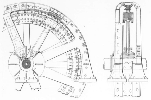
 |
| Fig. 11.Elevations, 500-Kw Motor-Generator Set. |
 |
| Fig. 12.Elevations of Engine-Type Direct-Current 2,500-Kw Generator. |
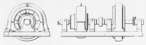
Figs. 9 and 11 show the 500-kw motor-generator sets. The synchronous motor is wound direct for 4,500 volts, and operates at 450 r. p.m. It, therefore, has 16 poles. The revolving element consists of a steel wheel, in which slots are milled to receive the dove-tails of the laminated poles. These revolving fields are mechanically so well constructed that they can stand the enormous peripheral speed of two miles per minutes, or more. The general construction of these synchronous motors is identical with the construction adopted by the Bullock Company for its revolving field alternators.
The direct-current machines that are to be installed by the Bullock Company comprise seven units, four being engine-type generators, rated as 450 kw, 150 volt, 120 r. p. m., and two rated as 500 kw, 300 volt, 450 r. p. m., which latter are to be driven by synchronous motors, and one rated as 2,500 kw, 300 volt, 75 r. p. m.
Fig. 10 shows the main features of construction of the four 450-kw engine-type generators. The field yoke consists of an annular cast iron ring, with inwardly projecting poles. The poles are built up of laminations of sheet steel in such a manner as to reduce to a minimum the effect of armature reaction. The poles are held in place by fillister-head cap screws. By taking out these cap screws it is possible to slide the poles out parallel with the shaft without disturbing either the armature or the field yoke. The armature spider has its arms milled at the outer ends so as to fit into dovetailed notches in the armature segments. This method of construction for armatures built up of segments produces an armature in which the stresses due to centrifugal force are resisted by the strength of the armature steel, and the only stress put upon the cast-iron spider arms is of a crushing nature.
The armatures of these machines are well provided with ventilating ducts and, as the armature coils are held in the slots by means of wooden wedges, these ventilating ducts are not closed by any bands or wire around the outside. The commutator sleeve is cast in one with the front end head of the armature, thus making the commutator an integral part of the armature.
In commutators having diameters equal to or greater than those in the present machines, the front ring is cut into segments to facilitate handling.
Fig. 12 is an outline of the 2,500-kw, 300-volt, engine-type generator. This machine has 48 poles with an external armature diameter of 20 feet. In construction it does not differ materially from the 450-kw generator described above. One feature shown in this drawing that is peculiar to the large engine-type generators of the Bullock Companys manufacture is the device for oscillating the rocker arm carrying the brush holders. By means of this addition, a motion of the brushes is obtained parallel to the shaft which is similar to the end play of the armature in a belted machine, whereby the brushes are prevented from wearing grooves in the commutator.
While the nominal rating of this generator is 2,500 kw, it is guaranteed to carry continuously a 25 per cent. overload, and is also guaranteed to have a full load efficiency of 95 per cent.
Additional land has been purchased adjoining the present station at Plum and Charles Streets, and the power house is to be enlarged by the addition of two 4,000-hp Reynolds Corliss engines, to be built by the Allis-Chalmers Company. These are to be of the combined horizontal and vertical type, similar to those being put in the Manhattan Railway power station, in New York. To one of these engines the above-mentioned 2,500-kw, direct-current Bullock generator, for supplying the outer mains of the Edison net-work, will be connected. On the other engine a 2,500-kw, three-phase, 4,000-volt alternator, also to be made by the Bullock Company, will be placed.
| |||
| Fig. 13.Cooling Tower. |
| |||
| Fig. 14.Roof View on Plum Street. |
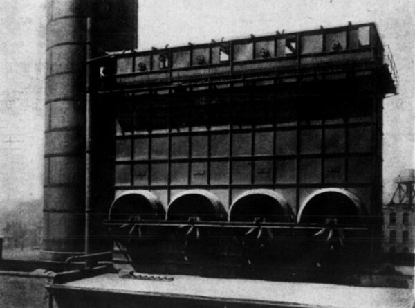
The present boiler plant has six 550-hp and two 300-hp Babcock & Wilcox boilers, with American under-feed stokers. The coal bins above these boilers provide for the storage of 2,000 tons of coal. The McCaslin conveyor system carries the coal from the wagons, where it is unloaded to the bins. The plant is all designed to operate condensing, as it adjoins the Miami and Erie Canal. Condensers are supplied by the Southwark Foundry and Machine Company, the central feature of the boiler room being an immense Weiss condenser. The condensers are supplied by a Birbus rotary pump, driven by Southwark engines. As it frequently happens that the powers that be see fit to let the water out of the canal without warning, it has been necessary to put a Wheeler cooling tower on the roof, which can be seen in Figs. 13 and 14. Fig. 14 is a view on Plum Street, showing the exit of the overhead lines from the station, along the canal. Many of these wires are soon to go underground, and some idea can be obtained from this as to the amount of the underground work necessary. In the new part of the plant are to be eight 550-hp Sterling boilers, equipped with McCaslin conveyors.
Near the center of down-town distribution the company has a large storage battery of the chloride type connected to its Edison three-wire net-work. This battery is on Government Place, near Fountain Square, in the building formerly used for the general offices of the Cincinnati Edison Electric Company. The battery capacity is 4,400 ampere-hours, discharging at a one-hour rate. The total number of cells is 166, and there are five cells on each side of the three-wire system which are not used. In connection there are two booster sets. Each set consists of two generators driven by a 175-hp engine. Each of the booster generators is capable of increasing the voltage on its side of the Edison three-wire system 70 volts, and of passing 800 amperes.
Since the consolidation much effort has been expended in systematizing the details of operation, so that the heads of departments might be familiar with everything going on over the entire system, and the exact condition of affairs. The company now has a large map of the city of Cincinnati, showing the location of every pole owned by the company. Such a map is, of course, of immense value, but is also the result of an immense amount of work after the consolidation of so many small companies, some of which kept no records of construction. The company has now some 15,000 poles planted in the city of Cincinnati. Mr. Pfiester makes extensive use of the card index system in keeping track of the details of construction and operation pertaining to the distributing system. In view of the completeness of this system, it will, no doubt, be of interest to reproduce here some of the cards used.
When transformers are installed their data and location are noted on a special card for the purpose, which is kept on file, a copy of which is here shown in Fig. 14. On this all the important information about the transformer can be seen at a glance. The first customer on the transformer is put at the top part of the card, and a space eft for other customers on another part of the card, as seen. On the back of the same card is a diagram of a city block and streets in blank, upon which the location of a transformer on a block can be marked and the street names and numbers filled in. With a card index of transformers properly kept up there is no danger of the overloading of a transformer, and much trouble is saved by being able to tell in a moment at the office whether additional customers can be put on any transformer and whether prospective customers are in reach of transformers already up. When a transformer is taken down or the wiring of a district remodeled, the cards are simply taken out of the index and new ones filed, so that the index is not burdened with dead records as would be the case with any bound-book system.
Records of arc lamps are kept on a card for the purpose, one of which is here reproduced. On the front of this card, Fig. 17, is the lamp number and make, with blanks for date of test and location. On the back, Fig. 18, are spaces for entering material and time expended in the repair of the lamp. As the company has heretofore had four types of lamps in use, there are four different colored cards. The front and back of the cards for the old Brush lamps are those here reproduced. Trimmers of street arc lamps make out a daily card report of the form shown, Fig. 19, and on the back of this report, Fig. 20, note is made of all defective poles, bases, cross-arms, wires, etc., that the trimmer sees on his route, and gives also the numbers of the lamps that failed to start when the current is turned on. In this connection it may be well to mention that each trimmer is required to O.K. his route every night before being let off for the day. That is, he must see that all the lamps trimmed by him during the day have started, and if they have not started to fix them before leaving. Routes are arranged as far as possible, so that trimmers will not have to travel far to see whether all their lamps have started.
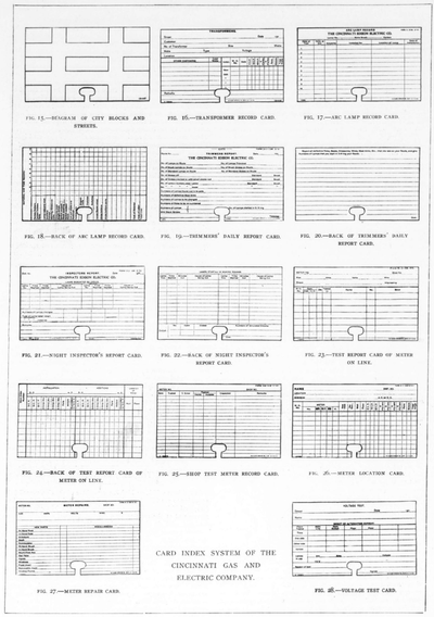 |
For the 3,408 city lamps there are 31 trimmers. There are 3,758 direct-current, constant-potential, enclosed arc lamps in commercial service, and 14 trimmers take care of this commercial work. Very close track is kept of the city street lamps, both by the police department of Cincinnati and by the company. Lamps out are reported promptly by the police department to police headquarters, and from there to the electric light companys offices. The man on duty at the latter office immediately calls up the inspector or trouble man in the district in which the lamp is out, giving him the number of the lamp. A book is issued by the company for the use of the policemen and the companys employees, giving the location of every street lamp in the city and the number of the lamp. Policemen in reporting lamps out, report simply the lamp number. Nine inspectors, or trouble men, are kept on duty all night to answer calls of this kind. Each man is given a certain district, so that in times of emergency a trouble man from one district may be transferred to another district if one man has more trouble than he can attend to. The inspectors of each district turn in a card report, Figs. 21 and 22, every day showing the lamps reported out, lamps started and lamps changed. As a check on this there is the record of the night telephone man at the electric light office, taken from the lamps reported out by the police department.
Meter inspection and repair records are also kept by a card index. This company represents probably the extreme in the matter of frequent taking down meters for inspection and calibration. The Thomson meter is the standard, though some others are in use. Every meter is taken down and tested in the shop once a year without regard to its previous record. In addition to this, every meter is tested in its place at least twice a year with indicating wattmeter and stop-watch. There are nine men in the meter department doing this work, and the company has about 7,000 meters, including those that are in service and those that are in stock and undergoing calibration. For testing meters on the line, a yellow card, Figs. 23 and 24, is used, and for shop testing of meters a white card, Fig. 25. For the location of meters a buff card, Fig. 26, is used, The record of meter repairs is kept on Fig. 27. Voltage tests are frequently made at various places over the system and records of these tests are also kept by a card index system, using the form shown, Fig. 28.
The rates for electric light are 10 cents per kilowatt-hour, with a sliding scale giving discounts as high as 40 per cent. for consumption for over 9 kw-hours per month per 16-cp lamp installed. In addition to the discounts allowed by the sliding scale, 5 per cent. discount is allowed on all bills paid within five days. For power, the rate is 10 cents per kw-hour, with a sliding scale allowing a discount up to 60 per cent. when over 800 kw-hours are used in a month. The total of incandescent lights and power now being supplied by the company amounts to a maximum equivalent of 340,847 incandescent, 16-cp lamps. A few of the down-town streets of Cincinnati are partially lighted, independent of the city lamps, by arches of 32 incandescent lamps. These arches consist of gas pipe extended from curb to curb. This lighting is paid for by the merchants along the street, $34 a month being received for each arch.
The capital stock of the Cincinnati Gas and Electric Company is $29,000,000, no bonds being issued. Of this about $9,000,000 is in the electric department.
In addition to the regular light and power business, the company is under contract to furnish power for the electric mules, as the electric locomotives are called, which are to supplant the mule on the Miami and Erie Canal. The Miami and Erie Transportation Company has built a track and ordinary overhead trolley along the towpath for this purpose. The lines of the Southern Ohio Traction Company for some distance out of Cincinnati will also use power from the Cincinnati Gas and Electric Company.
