[Trade Journal]
Publication: Electrical World and Engineer
New York, NY, United States
vol. 42, no. 3, p. 98-99, col. 1-2
Gold Pan Mining Plant at Breckenridge, Colo.
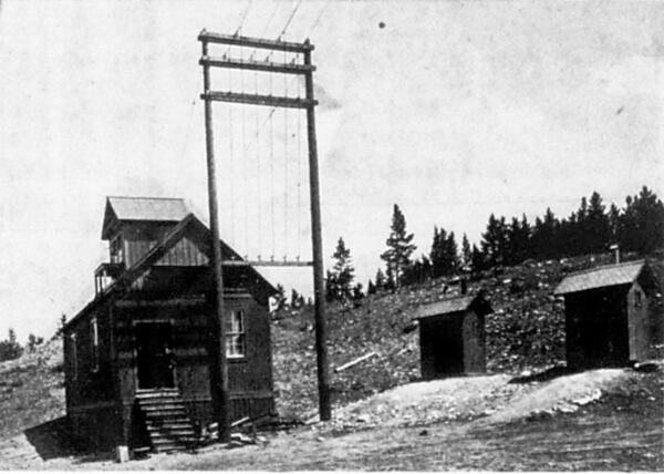
Breckenridge, Colo., is a growing mining town with a population of about 1,000, located 110 miles west of Denver, and practically in the center of the State. Here the Gold Pan Engineering & Mining Supply Company has recently entered quite extensively into placer mining and is probably operating the largest placer mine in Colorado. The center of the companys operations at present is shown in Fig. 1. In the foreground are seen two sets of vertical water pipes, which act as hydraulic elevators for raising the sand and rock to the flumes above. Water under high pressure is forced down one pipe and drawn up the other. The two ends are moved around wherever desired and the sand is drawn up with the water. These vertical pipes at present are 8o ft. long. They discharge into wooden flumes and the material is carried along over the riffles where the gold is separated and taken out. The rocks and refuse sand are carried away and dumped by means of the conveyor and trestle seen at the right.
| |||
| Fig. I.Placer Mine at Breckenridge, Colo. |
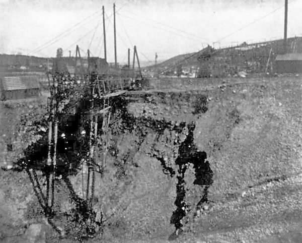
The Gold Pan Company is now installing a 150-hp induction motor in the pit shown in Fig. 1. This motor will drive a centrifugal pump to assist the hydraulic elevator in keeping the working free from surplus water. In order to handle large rocks and carry them out of the way two portable cranes of the boom type will be in- stalled. These cranes will run on tracks and each will be operated by a 30-hp Westinghouse induction motor mounted directly on the crane. Current will be supplied to the motors through flexible cables.
The power plant which supplies power for these motors is located on Spruce Creek, about five miles distant from the mine. Water is brought to the power house through an open canal for about a mile to a hill back of the station and then carried to the water wheels through steel pipe. The effective head under which the wheels operate is 425 ft.
| |||
| Fig. 2.Power Station on Spruce Creek. |
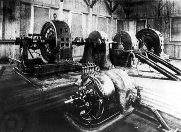
An interior view of the generating station is given in Fig. 2. There are two main water wheels of the Pelton type, each direct- connected through shafting to a 200-kw Westinghouse revolving field two-phase, 440-volt alternator. The arrangement of water wheels and generators is a novel and ingenious one, in that it provides a flexible means of connecting each generator to either wheel. The shafts of the wheels are parallel and are carried out with a coupling on each end. The shafts of the generators are normally connected to the Pelton wheel shafts in the manner indicated in the sketch, Fig. 3. Each generator is mounted on an extension foundation and is provided with a special moving lever (shown on one machine at the left in Fig. 2), so that it can be quickly moved from its normal position into alignment with the other waterwheel shaft and coupled up for operation. In this way both generators can be driven from either water wheel, and also each generator may be driven independently by either of the water wheels. In event of accident to either pipe line or to a water wheel or generator this flexible arrangement will undoubtedly be found of considerable value.
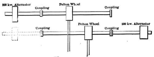 |
| F!G. 3.Diagram of Method of Coupling. |
For supplying exciting current there are installed two 11-kw, 125-volt exciters, each directly driven by a separate Pelton water wheel. One of these exciters is shown in the foreground in Fig. 2. This picture also illustrates the method of carrying flexible leads from the generator to a row of insulating blocks from which the wires run in a covered box to the switchboard. The flexibility of these leads allows the generator to be moved from one position to the other without disconnecting any wires.
Each water wheel has a gate valve controlling the How of water, but no automatic regulator is provided. The speed of the wheels is varied by means of the hand wheels at the end of long rods, which may be seen in the picture. These rods serve to raise or lower a hood in front of the nozzle, thus varying the direction and quantity of the water discharged. The nozzles are not of the deflecting type, such as are used on larger wheels.
| |||
| Fig. 4 Switchboard in Power Station. |
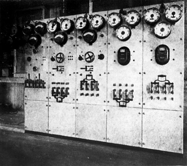
The station switchboard shown in Fig, 4 is built of blue Vermont marble and consists of five panels. The left-hand panel contains switches and instruments for both exciters. Panels 2 and 3 control the two generators, each being provided with two alternating-cur- rent ammeters, one direct-current ammeter, field rheostat and main generator switch. The remaining two panels control the two feeder lines leading to the transformers. Each panel is equipped with two ammeters, an indicating wattmeter, a polyphase integrating watt-meter and a four-pole, double-throw switch. Wattmeters of the indicating and integrating types are used, as the company sells a good deal of its current for power and lighting and the registrations are necessary in keeping the accounts of the customers. The switchboard has a double set of bus-bars so that the lighting and power loads, which are controlled from separate panels, may be thrown on either generator. At the left of the board on a swinging bracket are mounted voltmeters and a frequency meter.
| |||
| Fig. 5.Breckenridge Transformer Sub-Station. |
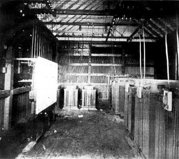
The two 440-volt, two-phase circuits are carried from the switch- board to the transformer room, located in a separate but adjacent building, where four 100-kw oil-cooled single-phase transformers raise the potential to 10,000 volts, three-phase, for transmission to a sub-station in the town of Breckenridge, five miles distant. The transmission wires are of No. 5 bare copper and are mounted on Mershon triple-petticoat glass insulators. The sub-station is shown in Fig. 5, the two three-phase, 10,000-volt circuits coming into the building at the right and the three four-wire, two-phase circuits leaving at the left. The transformer equipment in the sub-station, shown in Fig. 6, consists of five 100-kw oil-cooled transformers (one for reserve) used in stepping the 10,000-volt current down to two circuits at 2,000 and 440 volts. There are also three 25-kw transformers (one being in reserve) for supplying a 2,000-volt circuit for lighting. The company has a franchise for lighting the streets of the town with incandescents and also supplies a commercial in- candescent service, the distribution being at 110 volts. Enclosed arcs are also supplied for commercial lighting and are used in lighting the pit and grounds of the Gold Pan Company, as the mining operations are carried on continuously day and night. The 2,000- volt and the 440-volt circuits from the 100-kw transformers are used for the companys own power and also for customers in the vicinity, the power being used chiefly in lode mines for driving compressors, hoists, etc. Type C Westinghouse induction two-phase motors are used throughout. One 50-kw motor is used to drive the companys own machine shop where the hydraulic pipe used in the mining operations is manufactured.
The tail water from the power plant is carried down to the mine and is there used by the company for the hydraulic elevators.
| |||
| Fig. 6.Interior of Breckenridge Transformer Sub-Station. |
As the placer mining operations cannot be carried on during the winter months on account of the snow and the freezing of the water, the water power plant is shut down and a relay steam plant located at the mine is called into service for supplying the lighting load in Breckenridge. This plant consists of two 50-kw, 2,000-volt, two-phase Westinghouse alternators driven from a line shaft by means of a Corliss engine.
The water wheels at the power station were manufactured by the Pelton Water Wheel Company, of San Francisco, and all the electrical equipment was furnished by the Westinghouse Electric & Manufacturing Company, through its Denver office. Credit for the design of the power station and the other electrical equipment and the installation of all the plant is due to George H. Evans, engineer and manager of the Gold Pan Engineering & Mining Supply Company.
