[Trade Journal]
Publication: The Journal of Electricity
San Francisco, CA, United States
vol. 6, no. 2, p. 42-44, col. 1-2
Proceedings of the Second Annual Convention of the Pacific Coast Electric Transmission Association, Held at San Francisco, June 21, 1898.Concluded.
(Continuation from page 17, of last issue.)
MR. ENSIGN: The Redlands generators operate at 2,500 volts, supplying Redlands and the Union Ice Company direct. At this time of year, when the Ice Company's load is the highest, the Redlands load will run up to 30 or 32 amperes per leg, and the ice plant, with both pumps running, will average 45 amperes per leg. The ammonia compressor is a double-cylinder pump, 16x30, with cranks set 90 degrees apart, which, with only one pump on, will run as high as 30 or 32 amperes. With this load we could never notice the slightest nickering of lights in Redlands, which may be due to the synchronous motor used. To show how an induction motor will act on a fluctuating load, I may say that in the city of Riverside, where they have a recording ammeter in each leg of the circuit for keeping a record of the power used by the city, there is a 30 h. p. induction motor, operating a planing mill, giving a constantly fluctuating load. When that motor is working under an average horsepower of 8 h. p., as shown by the watt meter on the motor, the fluctuation on the ammeter represents a range of over 100 h. p. An induction motor, working on reciprocating apparatus, will cause fluctuations in the current to be multiplied enormously. This is the way I account for the difference between Mr. Eastwood's experience and ours; for even when a check valve becomes stuck in one of these ammonia pumps, there is no flickering in the lights at Redlands.
MR. LIGHTHIPE: There is a great difference between the lifting of water and the pumping of gas, as the gas is compressible. I have always had trouble in pumping water, especially in mining pumps, with anything outside of the triple plunger pump, probably on account of this long column of water, for every plunger, as it comes into action, has to change the speed of that column. Anything that is compressible, in the way of gas, will ease up the stroke.
MR. EASTWOOD: We have an ice plant of thirty tons capacity, operated by a 150 h. p. induction motor,also a 50-h. p. induction motor and a 10 h. p. induction motor,and we find no fluctuation whatever due to the ice plant, which runs twenty-four hours straight through.
MR. RIDLEY: It may be outside of the general trend of the discussion to talk about direct current, but I am rather inclined to bear out what Mr. Ensign says, that the fluctuation would come rather from the alternating current used than from any other cause. The Central Light and Power Company is operating a load that varies; a steady motor load of 150 amperes and a light load of 100, making 250, and it has the Sprague elevators running the load up to a thousand amperes, and we find no difficulty whatever in steadying our lights. We have no complaints from customers of fluctuation in light, and the only precaution that we have in any wise taken has been the diminishing of the fly-wheels of the engines and enlarging the steam ports; but I don't think we can get any better regulation than you could get from water power. The only point I would bring out is that I think this would show that the functions of the alternating current and also the influence of the line would possibly cause a great proportion of the fluctuation that is found in the plants which are operating with alternating machinery.
THE CHAIR: How do you reconcile that with Mr. Eastwood's statement that by using the same type of electric apparatus exactly, but upon different loads,a compressible gas load and an incompressible water load,that he finds the results very different indeed; one produces decided fluctuations in his lights and the other does not?
MR. RIDLEY: A compressible load will always save the fluctuation, naturally, but I consider that a Sprague elevator load is an incompressible load. [Laughter.]
MR. HUTTON: We are operating a compressor, located about a mile from the sub-station, which is driven by a 100 h. p. motor. Incandescent lights on the same circuit at the end of this line have considerable fluctuation when the compressor is working. It is a single-cylinder machine, but it does not affect the rest of the load outside of that one line.
THE CHAIR: There is one ever-fruitful subject of discussion, and that is the insulator subject, and I have been asked to bring it up, and I should have done so had I not been asked, because I was curious to know from Eastwood why he substituted glass for porcelain insulators after having used porcelain for some time, and I will therefore call on him first to give us any suggestions that he may have to make from his very fruitful experience on the insulator question.
MR. EASTWOOD: In the matter of insulators, the Folsom-Sacramento plant and ourselves were really pioneers, and in the matter of extreme long distance transmission our plant at Fresno has always held the lead until a short time ago, and, in fact, we now again hold the lead in long distance transmission. When we started in we, of course, took the apparatus which was offered us by manufacturing companies, in the condition that it was then worked out. We have, on our thirty-five mile line, a general electric porcelain insulator which was furnished at that time to both the Folsom-Sacramento and the San Joaquin plants. Of course, in the construction of the line, the insulators were shipped out in barrels, not put through any test, teamed out on the line, and then put up without any particular inspection. The first six months of the use of the line was during the dry season, and we had no difficulty with it, and were feeling quite happy in the belief that we had a pretty well perfected plant, so far as line insulation was concerned. Then came along the fogs of the following winterthe winter of 1896-7. It was a winter in which, in the San Joaquin Valley, the land fogs were of longer duration than had been known in a good many years, and the almost invariable rule is that in our climate there, whenever a low pressure era and a storm comes on, the fog will continue right up to the time of the storm, and then we will have a severe, heavy storm, which, in the course of two or three days, will be followed again by another land fog, which will continue on until the next storm, but it may possibly taper off and gradually disappear with quite a space of time between the fogs. During the heavy storms of that winter we had quite a good deal of difficulty from the burning off of the pins. I went into the subject pretty carefully, and I found that the pin almost invariably burned off at the point where the lower petticoat came in contact with the pin, and that in nearly every case where we had an insulator which burned off it was one that was cracked or defective in some way in the outer petticoat. The water from the rains and fog went down through the body of the insulator and formed a path for the current to the pin, and whenever we replaced any of these insulators where the pin had burned off, we always took great care to select sound ones, and at the same time we coated the pins with P. & B. paint, after being thoroughly boiled in paraffine. Since then we have had no recurrence of the burning of pins.
The matter of insulators has been discussed quite a good deal, and I have been watching very carefully all the discussions and all the different types of insulators that have been brought out, and have, in addition, made experiments in the matter of insulation to our own satisfaction. The conclusion I have come to is that for an insulator, the one main point on which you must be absolutely safe is the matter of having a dry space between your line and your pin. You must have a roof that will preserve an absolutely dry air space under the insulator in order to have perfect insulation for a high tension current; and for that reason, in making our extension to Hanford, we chose a glass insulator. There has been a great deal of talk about the hydroscopic qualities of glass, and the effect it would have, but the first 10,000-volt transmission line that was built used glass insulators from the first. It is running to-day, and we have never heard of such a thing as a pin burning off, from those peoplethat is, the Pomona plant. The type of glass insulator that was furnished us by the agents for the Locke insulator was such that I was satisfied it would give satisfaction. We made a very careful visual examination of all the insulators that were put on the line, and we made some static tests on them. These glass insulators are not only cheaper than porcelain, but they are better in every way. There is a good deal of argument as to the matter of strength. We will, in railway or incandescent work carry heavy copper wires on glass insulators that are very light compared with the ones used in transmissions, and yet we think we must have a very heavy, strong insulator to carry a No. 4 or 5 wire in transmission lines. As far as mechanical strength is concerned, our insulators will prove amply strong for any strain that will ever be upon them. We ran a voltage of 10,000 to Hanford as a matter of experiment, but as it was during the dry season, it was not a fair test. Our insulators are glass, with wooden top pin, and iron bolt and porcelain base, and I think that eventually some such type of insulator as this will be the one that will be finally adopted for all high tension transmission work. We expect, in the latter part of the fall, before the rains come on, when we get our high-tension line in operation, to change the insulators on our main line from the Fresno power-house to the same type of glass insulators that we have on the Hanford line. The porcelain insulators will give us no trouble whatever as long as the weather is dry. Just as soon as the wet weather comes on we will not feel safe in running our 19,000 volts on the porcelain insulators.
THE CHAIR: Bearing on the other side, as I know Mr. Ensign has made a number of very interesting experiments running up to 65,000 or 70,000 volts on porcelain insulators under conditions approximating a very severe driving rainstorm, I would like to have him give the association an account of his work there.
MR. ENSIGN: When we were trying to decide on an insulator for a 30,000-volt line, we heard all the opinions concerning the hygroscopic condition of glass, but we started out prejudiced for glass because glass cannot be punctured under such a voltage. I had satisfied myself that the trouble with the porcelain insulators used on the Folsom and Fresno lines was due to porosity, as could be demonstrated by breaking them open. The burning off of the pins was due to the current passing through the insulator to a point where the pin was wet close up under the lowest point of the threaded portion, at which point the potential, being sufficient to puncture the glaze where the insulator did not protect the pin from being wet, would form a small arc, gradually burning the pin off. But in looking for a glass insulator at that time, I could not find one large enough to stand the potential without the distance from the tie wire to the pin being too near the sparking distance of the potential used, so we were rather forced to the porcelain insulator, strongly guaranteed by the manufacturer. The insulator which we decided upon measures about six and one-half inches across the bottom by about four inches from the tie groove to the bottom of the outside petticoat, and instead of being round on top the top is squared down at the ends of the groove so as to give more of a right angle turn for the tie wire. They are sold to us under a guarantee not to puncture under a test of 70,000 volts. They will stand that voltage in dry weather with the top of the insulator immersed in water to the depth of the tie groove, with a terminal inserted in the pin-fit and the voltage applied to it, the pin-fit and grooves between petticoats being filled with a little water to help find cracks, if there are any. So far we have tested three carloads, which have been found very satisfactory.
I find that 66,000 volts, applied between the tie wire and pin, in ordinary dry weather, does not show the slightest tendency to jump around the insulator, although there will be a fine brush discharge in very foggy weather, sometimes jumping around with a sharp report, but not sustaining an arc. As this is four times the strain they will receive upon the line, we feel that it is a very satisfactory test.
The same insulator, mounted in the same manner as used on the line and tested for rain effect, showed a phenomena which has not been mentioned, to my knowledge, in connection with high potential insulators, which is that the height of the outside petticoat above the arm has a large bearing on the leakage and possibility of short circuiting during a rainstorm. In other words, the current seems to prefer to follow the path of the drops to the arm rather than jump across the shorter path to the pin. I took a potential of between 45,000 and 50,000 volts as being a safe voltage with which to determine the size of the insulator as regards rain for a 33,000-volt line. We turned the water on from a garden hose, using a very heavy spray, and gradually raising the insulators by putting porcelain washers on the iron pins, until we reached a height that would show no leakage, either by measuring the energizing current of the transformer or by a visible spark. We magnified the fluctuations of the energizing current by running the current through a water rheostat and connecting a 20 to 1 ratio transformer with the low potential side in multiple with the rheostat, putting a voltmeter on the 2,000-volt side, in that way magnifying the fluctuations of current enormously. These experiments were conducted in the dark, with hydrant water turned on in a thick spray. If the insulators were too close to the arm, there would be a fine, threadlike discharge to the arm from the outer edge of the insulator, and such a discharge would cause the voltmeter needle to swing violently. We found that at 45,000 volts, with the insulator four inches above the arm and a large number of insulators rigged up, we could absolutely detect no leakage. We then took these same insulators and raised them up six or seven inches above the arm, and raised the voltage to 60,000 volts. The leakage was still inappreciable.
| |||
| Ensign on Insulator Testing |
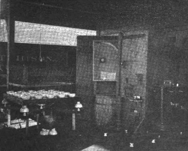
Our method of testing was to place twenty-five inverted insulators in a wood tray with water up to the position of the tie wire, one terminal of the transformer being placed in the water. Mounted on a framework were twenty-five iron pins, which could be dropped at once into the twenty-five insulators. Each of these pins had a spark gap one-sixteenth of an inch long between it and the wiring of the frame. When the insulator did not offer any leakage for the current, there would be no perceptible spark in daylight, but in the dark there would be a fine blue thread; but as soon as the slightest leakage occurred, it would change to a yellow color, and when the insulator would break down to a red flaming arc. I found some curious things in these tests, one of which is that it is of no use to test insulators without having a transformer of considerable capacity. You may get leakage from dust, or a weak insulator, which, while it will not break the insulator down, will not allow the transformer voltage to come up to the required test because of the C. R. drop in the secondary. For instance, with twenty-five insulators in the tray, and gradually raising the potential to say about 15,000 volts, the weakest insulator would break down; if we put another one in its place, perhaps the next time we would get to 20,000 volts and down would go another insulator, until finally we got the whole set of twenty-five to stand the 66,000. But as we would approach the limit, we found we would have to wait a moment or two to give the voltage a chance to rise without applying any more current to the transformer. This was especially noticeable if there was a slight leak, due to dust or dirt on the outside of the insulator. We had on a static voltmeter, which showed us what we were doing all the time. The tests which they made on insulators at Niagara Falls were made with a very small transformer, and some of the small insulators sent us broke down at about 15,000 volts.
We are pretty well satisfied that we have an insulator which will do our work, though I would prefer glass if I could get one large enough, at the same time free from cracks. I met a young man from Telluride, who said the only trouble they had with a five-inch glass insulator was if they shut down from any cause during a rainstorm they could not start up again. They have the same insulator which is used at Yuba River plant and that Mr. Eastwood is also using. I have tested one of these insulators, and the current will jump from tie wire to pin at between forty-five and forty-eight thousand volts. That was too small an insulator for us to use on our 33,000-volt line. When we are reaching these very high potentials, I think our insulators should be large enough to stand double the line potential between pin and wire. The time we decided upon our insulators we could not get a glass one large enough which was perfectly solid.
I have some photographs here showing method of testing which may be interesting, and will pass them around. We punctured between 15 and 17 per cent, of the first that were sent out. They had no method of testing at the factory.
MR. LEE: The glass insulator used on the San Gabriel line is a five and a half inch Locke insulator, weighing about four and three-quarter pounds, and designed for a working voltage of 20,000 volts, and I think the guarantee was that it would stand an insulation test of 40,000, which I think it will do. It is practically impossible to puncture glass that is sound, and it takes about 45,000 volts to go around it. If you take a hammer and hit a porcelain insulator on the head, where the tie wire is, sufficiently hard you will shatter it, and the same is true of glass; but if you only hit the petticoats, as a rule the outer petticoat is the one that will break. One great advantage in the glass insulator is that you can make a visual examination for cracks, which loom up very prominently. All you have to do is to clean the insulator over and you can see the cracks. The "checks" we have noticed in the ones shipped from the factory have not run over 1 per cent.
We understand these checks are due to the annealing of the glass. The question of the glass being hygroscopic is disposed of, because under the most severe conditions, that of a rainstorm, the hygroscopic features are lost sight of, and in dry weather both insulators will get covered with dirt. The Marysville glass insulators stood a test of about 36,000 volts on the line in dry weather.
MR. ENSIGN: I believe the insulator is good for 22,000 volts, and at that voltage perfectly safe in any kind of a rainstorm, but I would certainly limit it to 22,000 volts. There they were running at 40,000, and from my experience it was too small to stand 33,000.
THE CHAIR: I look forward to the time in the near future when we are going to eliminate the large element of copper cost from our calculations, and are going to run up to 50,000 volts as a common thing.
MR. ENSIGN: Our experience has been on one of our lines, and not a great while ago we changed seven Insulators in half a mile. It was a shotgun in that case. You could see the marks of the different shot, and the petticoats were all blazed off of one side and on another one all the way round, and there was nothing but the core left, and that was still carrying the wire, which had been thus carried through some severe rainstorms. I have known at least three insulators in the last year that have been that way. They were small insulators.
MR. EASTWOOD: We would be very happy indeed if we had not any more trouble than that which is caused by people shooting off petticoats.
MR. DE SABLA: We have very little trouble with our low voltage, but from what Mr. Ensign is saying about people shooting at insulators, we have both the porcelain and the glass, and we prefer the glass ones, as they are less attractive. All shooting is done at porcelain insulators, and we have not had one single shot at the glass insulators. So I will side with Mr. Lee in favor of glass insulators, on the ground that they are less attractive to the eye.
MR. LIGHTHIPE: Mr. Eastwood's remark about not having any insulators shot makes me remember that the Fresno line is so far away from anywhere that nobody can find it. On the road to the power-house you see the line about once; the rest of it is several miles away from the road off on the top of a mountain. A great many lines run along the county road, and there is where the insulator gets it.
On motion, the Convention then adjourned.
