[Trade Journal]
Publication: Street Railway Journal
New York, NY, United States
vol. 28, no. 20, p. 962-969, col. 1-2
THE WINONA INTERURBAN RAILWAY
A passenger on the recently constructed interurban railroad between Warsaw and Goshen, Ind., may get some comfort from the fact that the portion of his fare usually devoted to the payment of dividends will be used in the maintenance of a trade school for the education of children who would otherwise be unable to obtain an education. The Winona Interurban Railway Company operating the line is a branch organization of the Winona Assembly and Summer School Association, which is most widely known through the Winona Assembly conducted by it during the summer months at Winona Lake, Ind. This assembly is carried on in a manner somewhat similar to the original New York Chautauqua Assembly, in a park embracing 2100 acres of land lying about Winona Lake and two miles east of Warsaw, Ind. The trade school already mentioned is conducted in the park throughout the year, and the students and instructors in the school, together with other permanent residents, bring the winter population of the park up to about Ivo. The attendance during the summer, however, is about 450,000 people. It is partly for the purpose of furnishing &tier transportation facilities to this park that the Winona Interurban Railway was organized. The success of the Winona & Warsaw Railway, which is operated by the Winona Association between Winona Lake and Warsaw, facilitated the sale of the bonds for the new interurban line. This small road, after two years of operation, had earnings sufficient to meet the interest on its bond issue and a 6 per cent dividend on an amount of capital stock equivalent to the amount of the bond issue.
| |||
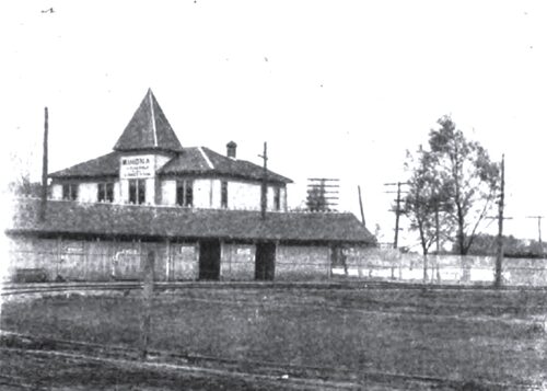
| Terminal at Winona Lake |
The organization of the Winona Interurban Railway Company, operating the Warsaw-Goshen line, is unique. Fifteen directors of the Winona Assembly are directors of the railway company, and each holds in trust for the assembly $1,000 of the total of $15,000 of stock issued by the company. The stock simply represents control and the road was constructed entirely on a bond issue.
|
| |||
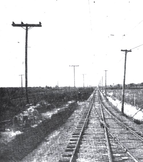
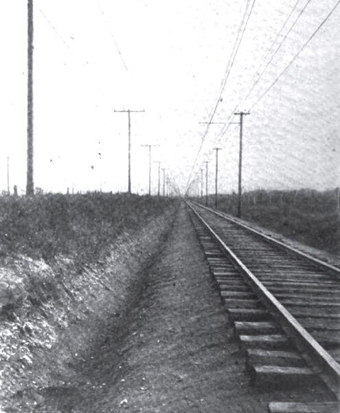
| Long Tangents on the Line of the Winona Interurban Railway |
The Warsaw-Goshen line, with which this article is mainly concerned, is only one division of an extensive system planned by the operating company to center at Warsaw. The line already constructed extends north of Warsaw to Goshen, 25 miles. A line south of Peru, 45 miles distant, will be put into operation within a few months, and plans are under way to extend lines east of Warsaw to Fort Wayne, 38 miles distant, and west 65 miles to Valparaiso, Ind. The east and west line will be built along a direct line from Fort Wayne to Chicago, while that extending from Peru to Goshen will connect the interurban railway systems in the northern portion of Indiana with those surrounding Indianapolis.
The Warsaw-Goshen line was constructed almost its entire length on a private right of way, through a rich farming country averaging in population about 1200 people per mile, exclusive of terminal cities, of which Goshen has a population of 10,000 and Warsaw with 5000 people. It connects several trunk steam road lines running east and west and thereby makes connections for steam road passengers en route to Winona Lake.
| |||
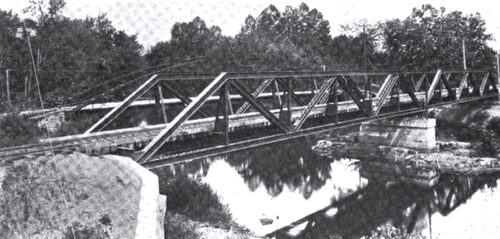
| Bridge Over Elkhart River |
The Electrical Installation Company, of Chicago, carried out the contract for the construction of the complete railway system. The contracts for the power house, sub-stations, and the electrical equipment of the cars, however, were sublet by the Electrical Installation Company to the Allis-Chalmers Company, of Milwaukee. Sargent & Lundy, of Chicago, who designed the power house and sub-stations, acted as consulting engineers for the railway company.
TRACK AND ROADWAY
The line traverses comparatively level country, and as a consequence very little excavatink and filling were required to get a roadbed free. from excessive grades. However, a t2-ft. fill was necessary at the approach to a bridge over the Elkhart River, and at another point on the line a it-ft. cut was made. The maximum grade on the line is 04 per cent and is about moo ft. long. long. At one point a to-degree curve could not be avoided because of the topography of the country, but with Oils exception the line is free of sharp curves.
The only steel structure on the line is a two-span pony truss bridge over the Elkhart River, a few miles south of Goshen. The' spans, which rest on concrete footings, are 96 ft. long and are designed to support a train of 6o-ton cars. The only other structure worthy of mention is a 5oo-ft. trestle over a sink-hole north of Milford. The Big Four Railroad, which parallels the electric line, crosses this sinkhole on a fill Which has caused the operating company an endless amount of annoyance, and to avoid the possibility of similar trouble it was thought best to trestle over the sinkhole. The ground at this point is of such a nature that a 20-ft. gas pipe sank into the ground its full depth by its own weight. The piles for the trestle were 70 ft. long and were driven into a bed of solid gravel.
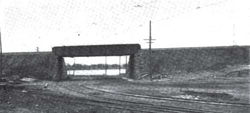
| |||
| Under Grade Crossing Near the Terminal at Winona Lake |
The width of the roadbed is 15 ft. and the cuts, including ditches, are 20 ft. wide. The slopes are all 1 1/2 ins. to 1 in. The line is ballasted with 8 ins. of gravel under the ties. At some points, where the road is built on a gravel deposit, ballasting is done at very little cost. The gravel is simply dug out of the right of way and shoveled over on the track. Chestnut ties 6 ins. x 8 ins. x 8 ft. in size and rails of standard cross section and 70 lbs. in weight are employed. Outside of city limits the joints, which are made with four-bolt angle plates, are bonded with American Steel & Wire Company' soldered bonds placed on the ball of the rail. In the towns, however, a compressed terminal bond is used. The two rails are cross-bonded at intervals of ten poles, or 1000 ft.
Sidings 500 ft. long are located 4 miles apart. At the present time the switch stands are lighted with oil lanterns, but it is the intention to equip and wire them for electric lights.
Two grade crossings are made with steam road tracks. At New Paris, where the tracks of the Wabash Railroad are crossed, interlocks are installed. It is the intention to avoid the present grade crossing with the Baltimore & Ohio Railroad at Milford Junction by the construction of a viaduct.
THE NEW POWER STATION
A new power station was built near the entrance to the Winona Assembly grounds and adjacent to Winona Lake. It is constructed on a plan which permits future extensions to be made without interference with the operation of the portion of the plant already in service.
The building consists of a steel frame with walls of red brick. The roof, which is liberally provided with skylights, is of cinder concrete. The floors are also of concrete., Two trans-verse fire walls divide the interior of the building into three sections, a coal storage room containing an elevated standard-gage track, a boiler room, and an operating room containing reciprocating engines, having below it a basement consisting of a high-tension bus structure compartment, a toilet room, and a room surrounding the engine foundations in which the condensers are located.
·
·
The high-tension bus structure in the basement, after extending almost the full length of the building, near the west wall makes a right-angled turn in order to reach the transformers of the sub-station and of the auxiliary apparatus. When the west extension to the building is made the bus structure will be extended west so that the whole structure will be T-shaped. The structure is built of repressed brick with concrete barriers. The three compartments are built one above another and the bus-bars of No. 2 bare copper wire are supported on Locke No. 408-B high-tension insulators. Near the east end of the structure the taps are taken off the buses for the outgoing high-tension lines. These after being carried through a high-tension oil switch are heavily insulated and enter vertical ducts in the wall of the building which lead to the lightning arrester compartment, built above the roof trusses at the northeast corner of the building. Specially constructed walls. Two pieces of bituminized fiber 1 ½ ins. and 4 ins. in diameter, respectively, are placed concentric inside a shorter piece 6 ins. in diameter. The three pieces are held separate from each other by wooden bushings, and the whole is placed in a is-in. vitrified tile in the wall of the building. The high-tension wire enters through the central conduit.
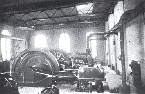
| |||
| General View of Interior of Generating Station |
The auxiliary and sub-station apparatus in the west end of the station consists of a 300-kw Allis-Chalmers rotary converter with reactance coils, transformers and oil switch, the steam-driven exciter already mentioned and a motor-driven exciter set, together with a transformer and oil switch. Space has been left for an additional rotary converter, and this, together with the necessary transformers and oil switches, will be installed immediately. The motor generator exciter set consists of a 75-hp, three-phase, 375-volt induction motor direct connected to a 50-kw, direct-current, 120-volt Allis-Chalmers generator. Current for the motor is obtained from the high-tension buses in the basement. Leads from these, after passing through an oil switch, go to a 75-kw oil-cooled Allis-Chalmers three-phase transformer which lowers the voltage to that required for the motor. The rotary converter transformers are of the oil-insulated self-cooling type, and are of 110-kw capacity each. The secondaries are connected to the converter through a set of reactance coils having a rating of 45 W. V. A.
·
·
STATION LIGHTS
The station is well lighted by arc lamps suspended from ornamental brackets bolted to the walls and by clusters of incandescent lamps placed on the walls and at other convenient points.
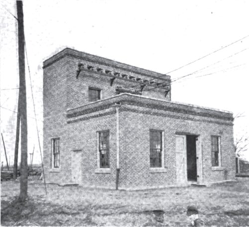
| |||
| Exterior of Sub-Station at Goshen |
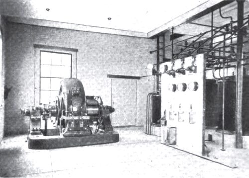
| |||
| Interior of Goshen Sub-Station |
THE HIGH-TENSION LINE
After leaving the station the high-tension wires, consisting of No. 4 copper conductors, are carried on a separate pole line to two sub-stations, one at a point midway between Warsaw and Goshen and the other at the southern limits of Goshen. The high-tension poles are 35 ft. long and are spaced 125 ft. apart. The three conductors are carried on a single cross-arm 10 ft. long, which is secured to the pole by means of a brace of angle iron in addition to the usual bolt at the gain. Two of the 408-B Locke insulators are located on one side of the pole at a distance of 34 ins. apart, while the remaining one is on the end of the cross-arm nearest the track. The lines are transposed every 10,000 ft. Through towns the high-tension line follows the track, but in corporate limits, and at highway crossings as well, extra high poles are employed. Where telephone lines are crossed, suitable baskets serve to protect these latter lines in the event of breakage of the high-tension conductors.
LOW-TENSION LINE
Outside corporate limits of towns, the single 3-0 grooved trolley wire is supported by a bracket pole line 21 ft. above the track. The poles, practically all of which are chestnut, are 30 ft. long. They have 7-in. tops and are set 100 ft. apart. The butts of these poles, as well as those of the high-tension line, are treated with Carbolineum. A single cross-arm carries two. No. 9 iron extra BB telephone wires and a 700,000-circ.-mil aluminum feeder. In corporate limits the feeder is covered with insulation, but is otherwise bare. At intervals of ten poles, or moo ft., it is tapped in on the trolley line by means of regular feeder clamps and 2-0 lead-in wires. Garton lightning arresters are located on every twentieth pole a few feet below the bracket arm. These are grounded both to the rail and to a A-in. gas pipe driven in the ground. At intervals of one-fourth mile, and at sidings as well, telephone jack boxes are located on the poles.
·
·
SUB-STATIONS
The two sub-stations are of similar construction. The brick buildings measure 31 ft. 6 ins. x 28 ft. inside, and are intended for an ultimate installation of two 300-kw rotary converters. The high-tension wires enter what might be termed a lightning-arrester tower over the rear portion of the building through entrances similar to those used in the walls of the power house. After passing through disconnecting knife switches and the lightning-arrester choke coils the high-tension conductors drop down the rear wall of the building to the bus-bars and the hand-operated oil switch located on the main floor. They then drop to the 110-kw Allis-Chalmers step-down transformer on the floor underneath the bus-bars. The secondaries of the transformer pass through a reactance coil and then descend into the bituminized fiber conduits leading underneath the floor to the pit in the center of the rotary converter frame. The direct current leads from the converter return underneath the floor to the switchboard at the center of the building and then rise to the top of the building and leave through exits just below the high-tension entrances. The relative location of the apparatus, it may be observed from the plan presented, is such as to require the least amount of wiring. The wiring, in fact, makes one continuous loop of the station and in no case doubles back on itself.
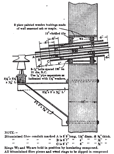 |
| 33,000-Volt Entrance of High-Tension Line Into Power Station |
·
·
