[Trade Journal]
Publication: The Journal of Electricity
San Francisco, CA, United States
vol. 5, no. 9, p. 169-172, col. 1-2
The Provo-Mecur 40,000-Volt Transmission
By LEON W. BLY
BUT few, even in the electrical transmission fraternity, are aware of the fact that the highest voltage employed in the commercial transmission of power over a long distance is that which is now operated on the lines of the Telluride Power Transmission Company between Provo canyon and Mercur, Utah. The Telluride people are pioneers in the field of extremely high voltage transmissions and for several years have experimented conjointly with the Westinghouse Electric and Manufacturing Company, on transmission lines with potentials ranging as high as 120,000 volts.
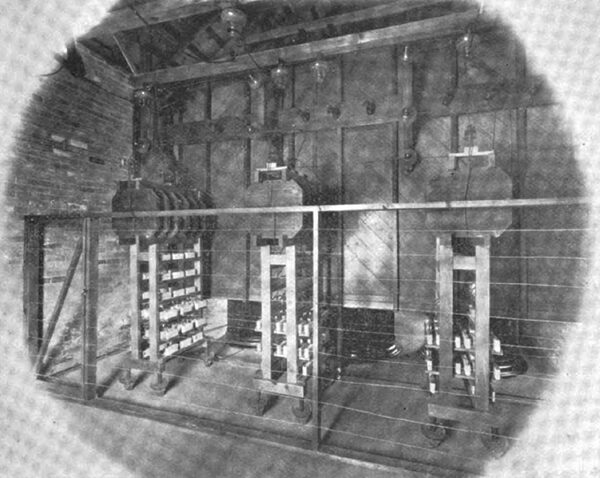
| |||
| Fuses, Choke Coils and Lightning Arresters on the Provo-Mercur Transmission. |
The line used for carrying out these experiments was a special one extending from the Telluride Company's power house near Ames, Colo., to the Gold King mine and having a length of 11,720 feet. The route of this line was over a rugged country subject to a heavy fall of snow in the winter and rain with severe lightning in the summer. The poles were placed one hundred and eighty feet apart and supported three circuits of No. 8 galvanized iron wire. Practically all the different varie¬ties of cross arms, pins and insulators to be found on the market were tested as were also many new models of these appliances, devised at the time, and during the test runs, the condition of the atmosphere and of the line in regard to snow, rain, humidity, were carefully noted. Up to the present, the results of these important experiments are reserved and every effort to secure the data deduced has been unavailing.
Reverting to the Provo-Mercur transmission, the plans of the Telluride company contemplate the early installation of two thousand horse power, in two units of 750 kilowatts each, to furnish power and lights to the mining interests in and about Mercur and Tintic, Utah. These two districts, which are perhaps twenty miles apart, are respectively thirty-two and forty-six miles from Provo Canyon, where the power house is located. The Provo-Mereur transmission line is the one which has been placed in operation, but work has been commenced on the construction of the independent line from Provo Canyon to the Tintic district, which will be, as stated, 46 miles in length. After the Provo-Tintic line is completed, the sub-stations at Mercur and Tintic will be connected together by a subsidiary transmission line so that in case of an accident to either main line from Provo, service may be continued without interruption to both places. Immunity front pole line trouble seems to he perfectly secured by this arrangement as the two pole lines take entirely different routes.
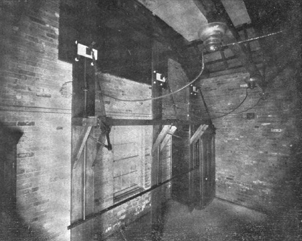
| |||
| Break Switch for 40,000 Volts on the Provo-Mercur Transmission. |
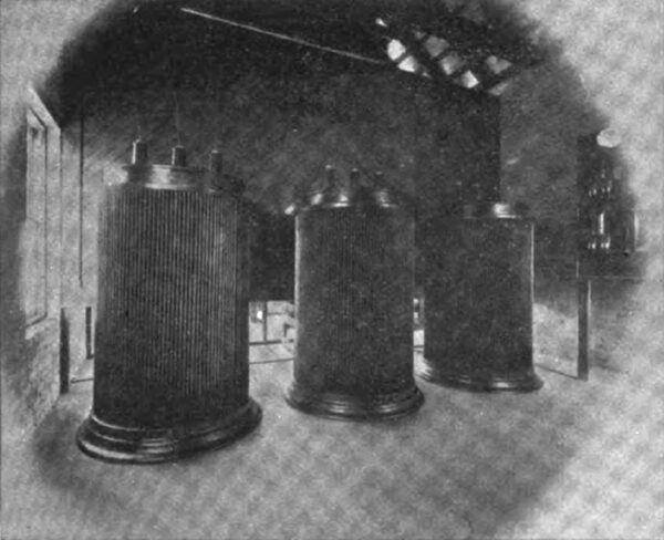
At present, one 750 kw. type "A. P." three phase General Electric generator is being operated by a flexible connection to a turbine wheel driven under a head of 125 feet and running at 300 revolutions the turbine being temporarily hand-regulated. This generator has a periodicity of sixty cycles, is star wound, and gives a phase potential of 300 volts. Of the four 250 kw. raising transformers installed in the generating station, but three are in use, the remaining one being as reserve and its connections are so arranged that it can be substituted in service for either of the other transformers at a moment's notice. The normal primary potential applied to the raising transformers is 462 volts, the normal secondary being 23,100 volts. As is the ease with the primaries, the secondaries are connected in star, hence the three phase high tension terminals have a phase pressure of 40,000 volts.
The principal material used in the insulation of these high tension transformers is muslin and fullerboard, blocks of maple wood being used to separate the coils. The transformer cores and coils are immersed in mineral seal oil, with no other cooling device than that of the natural radiation of heat from the surfaces of their cases. This radiation is however, very great because of the fact that the surfaces of the cases is rather deeply corrugated. To be exact, the corrugations are 2 1/2 inches deep and one inch wide. The general appearance of the high tension transformers is shown in the illustration appearing on page 171, which also shows plainly the method of supporting the interior high pressure circuits.
The high tension leads are brought out of the tops of the tanks through walnut bushings on the inside of each of which is a heavy porcelain tube extending from the top of the bushing down into the tank beneath the surface of the oil. The low tension leads are brought out at the sides of the tanks and these low tension leads consist of two series of twenty-eight turns in multiple of two three-quarters inch by 349 mils strap copper. The high tension windings consist of 1400 turns of No. 9 magnet wire. These transformers, as well as the lowering transformers at the Mercur sub-station, were built by the Wagner Electric and Manufacturing Company, of St. Louis, Mo., upon the designs and specifications of the Telluride Power Transmission Company.
Tests made the writer show the copper loss of the transformers to average about 2150 watts; the iron loss is about 3030 watts; the normal temperature at full load is 118 degrees above that of the surrounding air.
Three phase generation, three phase transmission and two phase distribution constitutes the scheme of the polyphase equipment, and all the three phase portions are star-connected and the common center or neutral point of the star is grounded as shown in the circuit dia¬gram of connections on page 172. Moreover the two phase distribution is grounded as will be described later. The line is protected by the Wurts non-arcing lightning arresters.
The line, which is carried on 35-foot cedar poles placed 125 feet apart, is of No. 5 B. & S., medium hard drawn copper supported so as to form the points of an equilateral triangle having six-foot sides. One of the three wires is placed on top of the pole and the remaining two are run on the respective insulators of a seven foot cross arm with a separation of six feet between the pins. The wires are not transposed, and a metallic telephone circuit is carried on brackets at a distance of 42 inches below the cross arm.
| |||
| The 40,000-Volt Transformers. |
The insulators are of a special type of triple petticoat glass, having two corrugations around the top below the groove designed to carry the line wire. This arrangement not only has the advantage of increasing the surface of the glass between the wire and pin, but it also protects a portion of the surface from extreme moisture during rain storms. The approximate dimensions of the insulator are 6 1/2 inches across the base by 6 inches high, and the insulator is supported by a specially long locust pin made proof against moisture by being boiled in paraffine. Great care was taken to fill the pores of the wood thoroughly, to effect which the pins were kept in the tank in which they had been boiled until they had become thoroughly cooled, after which the surplus wax was removed and the surface of the pin was made smooth by dipping it again in very hot paraffine wax. These pins, being extra long, supported the insulator clear of the cross arm by five inches and the pin used at the top of the pole is two inches longer still, making the separation between the top insulator and the pole to be seven inches.
It appears obvious that an insulator of this design will offer a high resistance to a discharge over its surface, but should it be assumed that it could reach the lower edge of the outside petticoat, there would be little inducement for it to go further as the pin is at all times a good insulator and its surface is of such a nature that a film of moisture will not collect over it. On several occasions insulators have been shattered by marksmen, but it has been the experience that if trouble developed owing to the grounding of the wire on the pin or cross arm, it would promptly rectify itself by the burning off of the cross arm, leaving the wire without support at that pole.
It will be interesting to note that at each pole along the line one can hear crackling from static discharges at all times, and during certain atmospheric conditions, the insulators are dimly luminous with pale phosphorescence. The line itself, however, is non-luminous at all times except for the brush discharges which sometimes exist from points of the line, such as from the tips of the tie wires.
The lightning arresters, as before stated, are of the Wurts type. About twenty-five arresters being kept between the line and the ground. Six choke coils are used, and these are placed edgewise on top of the arrester racks, and as the latter are designed to be as compact as possible, they measure over all but 2 feet, by 34 feet, by 7 feet high. One of these banks of lightning arresters and choke coils are connected in each line wire as shown in the illustration on page 169.
To be more explicit, the connections of the lightning arresters are arranged as follows: Six choke coils are coupled in series and cut into the line after leaving the transformers. For convenience, we will designate the choke coils by numerals consecutively, coil number 1 being at the left and being connected direct to the line. On the line side of each coil numbered 1 and 2, three Wurts arresters, each containing seven non-arcing cylinders, with about one-twentieth inch gap, are tapped off in series, there being thus two series of three arresters each, for the first two coils. The free ends of the two series of arresters from coils numbered 1 and 2 are closed together, the connection thus formed being termed "point a." Similarly the two series of arresters from coils numbered 3 and 4 are connected at point b, as are also the two series of arresters of coils 5 and 6 at point c. From points a and b are then carried a single series of five arresters, the ends of these series being joined at the point d, while from point c is run a single series of eight arresters which are connected to (at point e) the terminal of a single series of three arresters between d and e. Eleven choke coils therefore, intervene between point c and either of the six choke coils referred to, while from point a is continued a single series of fourteen arresters running to ground. About twenty-five arresters intervene between any choke coil and ground while a minimum of six arresters are across a coil.
Two further features of interest, also shown in the engraving last referred to, are found in the fuses inserted in the high tension wires, and in the high tension switches used. Each of these three fuses, consists of a single No. 30 B. & S. bare copper wire, thirty-six inches in length, over which an asbestos tube is drawn. The fact that three such thread-like wires will carry a load of over seven hundred horse power, is as increditable to the layman as it is evident to the electrical engineer who fully realize the significance of transmission at a potential of 40,000 volts.
The high tension switches, illustrated on page 170, are inserted on each of the three line wires. They are rigidly connected together so as to be operated by a common switch bar as shown, and each give to a six-foot break, the separation between the switches being five feet.
The sub-station now in operation is installed in the Golden Gate mill, at Mercur, which is believed to be one of the largest, if not the largest, cyanide mill in the world. Its electrical equipment, aside from the induction motors used for mining and milling purposes, and as about to be described, consists of three, 300-kw. lowering transformers by means of which the 40,000-volt three phase line current is reduced to 220-volt, two phase current, used for lighting and for operating Westinghouse two phase type "C" induction motors. The plan of connections for the step-down transformers is shown in the sketch on this page, which is a comprehensive outline drawing of the electrical connections of the entire equipment from the generator to the ultimate motors and incandescent lights operated by the system.
These lowering transformers are the same in general design as the raising transformers in the power house at Provo Canyon, and differ therefrom only in capacity and voltage. It will be noticed too, that, as is the case in the generating station, an extra transformer is installed for emergency use-and its connections are so arranged that it can be substituted for either of the other lowering trans¬formers with celerity.
·
·
