[Trade Journal]
Publication: Telephony
Chicago, IL, United States
vol. 5, no. 6, p. 352-353, col. 1-2
PRACTICAL TELEPHONY
Conducted by P. KERR HIGGINS A. M. I. E E.
ARTICLE VII.
Pole line construction divides itself into five important divisions: (1) Poles. (2) Cross-arms. (3) Insulators. (4) Wire. (5) Guying. In general, it may be said that the most expensive part of the plant per subscriber is the outside plant; hence, the importance of constructing it well and at the same time as reasonable as' possible. Nowhere, perhaps, can money be wasted as in outside construction, therefore great care should be taken to use only the best material.
|
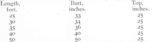
Poles.These are of two kinds, (1) line poles; (2) terminal (or cable) poles. The line poles are those used in the straightaway work and support the wires between the terminal pole and the office or between two terminal poles. They are usually lighter than the terminal poles, because they are not called upon to bear as heavy a strain. It is customary to select the heavy poles for terminals and set them aside for that purpose, iron poles are also used for terminals. All poles should be of the very best quality, live cedar or chestnut. For work in the city the poles should be selected as to straightness, the best being used for street work and the cullings for alleys: the following gives circumference usually demanded by engineers:
 |
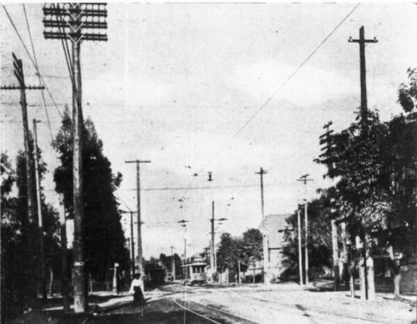
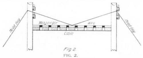
The number of poles along a given route must be a predetermined factor, and is governed by the route and the obstacles met. In toll line work forty poles to the mile is standard, but no definite rule can be applied; on light leads twenty poles are sufficient. An arrangement of this kind enables one to double the poles per mile by setting an additional pole in each span as the number of wires (or load) increases. All poles on being received should be carefully examined and handled with care in unloading. In planning a pole line it is customary to place wooden stakes at pole locations. The size of the pole may be indicated by the color of the stake, and a different color for each five feet on the stake may be placed the number of cross-arms, etc. In city work this need seldom be done but for toll lines it is found necessary. All guy stubs should be marked and located in a similar manner. In locating poles in the city, in order to retain the good will of the people, it is well not to abuse the privilege of planting a pole. against the will of the property owner, even if the law is on your side. A small piece of cable here and there will be beneficial to your system and avoid conditions as shown in Fig. 1, which is an actual condition in a prominent street in Los Angeles. Cal. It will be noticed that on two corners there are no less than ten poles. It is good policy in a case of this kind to make an effort to plant the pole and then make other arrangements, if necessary, installing a short piece of cable and using a longer span as in Fig. 2. In digging post holes, it is well not to leave them open over night, especially in the city, and if necessary to do so they should be properly protected. The depth to which they should be dug for the various sizes of poles is usually as follows:
 |
The modern method of setting poles in the cities is by means of a derrick wagon as shown in Fig. 3, which is quicker and cheaper and less liable to accidents. As a rule, the old method of "picking" is still done on toll lines, although I believe on a heavy lead the derrick wagon would pay. In average soil one man should dig eight six-foot holes in ten hours.
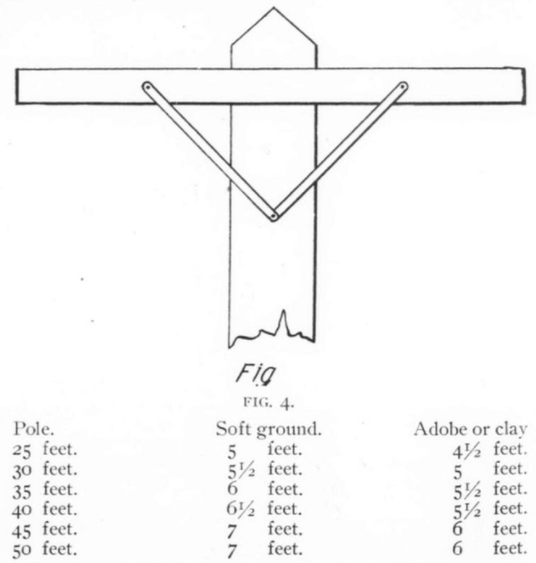 |
In setting poles at corners, give lean of twenty inches against strain. The distribution of poles is usually done by wagon and the heavy poles are used as terminal poles and for corners. Poles should be set so as to have the cross-arms of the alternate poles face in opposite directions. The pole having been set in place, it should be held there by means of pike poles while the alignment is being made. In cities it is well to thoroughly tamp the ground after pole setting and mix broken stone with the earth, then cement around the pole for about one foot ; this usually prevents caving in and unsightly holes at the base of the pole. The cement should be so arranged as to drain away from the pole. In the country the earth should be banked up slightly so as to throw off the water and allow for the settling of the ground. The setting of poles in river beds, etc., is usually done by placing them in a barrel filled with rock or stone and sand. The poles should have gains cut for the cross-arms and tops roofed before setting. On light leads and on toll lines the pole is often fully equipped with cross-arms, etc., but in the city this is not necessary. All gains, roofs, etc., should be painted with two coats of pure white lead. The tops of all poles should be roofed at an angle of 45deg (Fig. 4) and gains cut twenty-four inches apart, the depth being one half inch and the width four and one-fourth inches. They must be square and true with the axis of the pole and other gains on same pole. The first gain is usually eight inches from top of poles.
Quality of Poles.All poles should be of best selected, straight, live growth timber, with butt and top squared; free from splinters, bark, stumpage, dry or wet rot, all knots closely trimmed.
Guy Stubs.The material used for these should be equal to that in use on the pole line as to quality and in some cases as to appearance, the guy stubs should be not less than twenty-four inches in circumference at the top. All anchor logs should be at least twenty-two inches in circumference and six feet in length.
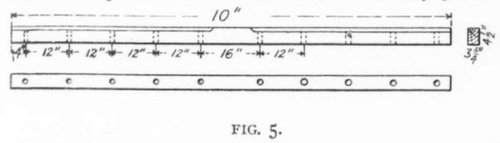 |
Cross-arms.Ten pin cross-arms are standard for the average lead and it is seldom found economical to use less. These cross-arms are sawed from close grained heart wood selected yellow-leaf pine, thoroughly seasoned, kiln-died, and free from sap-wood and knots, and measure four and one-half inches by three and one-fourth inches and are ten feet long, as seen in Fig. 5. The top of the cross-arm should be chamfered to a radius of forty degrees leaving a ten-inch space uncut in center so as to fit snugly into the gain. The pin space is divided up as shown in Fig. 5. The cross-arm should be bored for one carriage bolt, two lag screws and two brace bolts. All braces should be thoroughly galvanized and be subject to an acid test, these are usually twenty to twenty-eight inches long, one and one-fourth inches wide and three-sixteenths inches thick with a hole in each end.
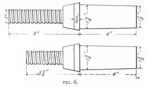 |
Pins.Pins are made from two woods, locust and eucalyptus; the latter is coming into strong favor and presents a much neater appearance than the locust; they should be of the best quality and free from knots and soft wood. The size and dimensions are shown in Fig. 6, being used in two sizes, for straight line work and for transpositions. The pins are held in place by wire nails driven through the cross-arm at the base of the pin. The completed cross-arm should be given two coats of black metallic paint, the paint usually used is a mixture of carbon gas black, boiled linseed and B. & T. drier.
Insulators.These are generally of glass, but porcelain knobs arc often used to advantage where there is no drip toward the wire. The glass insulators are of two kinds
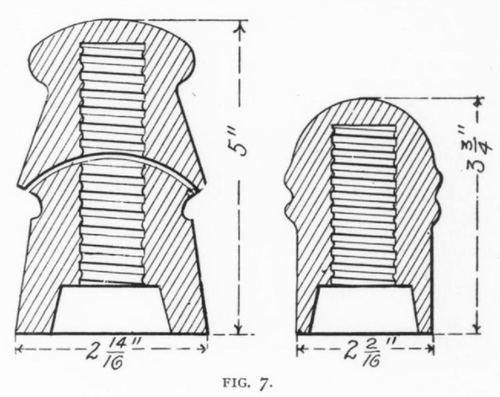 |
for straight lines and for transpositions, as shown in Fig. 7; sometimes the double-grooved insulator is used for transpositions and simplified construction and is much cheaper. The insulator should be free from cracks, points and other defects.
Protection of Poles.Considerable damage is done to poles by horses and by vehicles colliding with the poles. To avoid this as far as possible, protectors are used in the shape of strips of galvanized iron fixed and nailed one and one-half inches apart. Sometimes a number ten galvanized wire is wrapped around the base for a height of five feet.
